3
MS 41R / MS 43R / MS 45R / MS 45R-G
2
3
5
4
1
00.05.01
Brown
Blue
90-250 V
Black 1
NO
Black 4
NC
Black 3
Relay switch 8 (3) A 230 V
Activated
Sensor
Not activated
Mode indicator
Is activated individually
for adjustment
Colour: Adjust:
Press A Press B
Green Sensitivity
Red
Delay
Min.
Sec.
Yellow Switch on/off
Switch-on
Switch-off
Flash
Constant
Activate both buttons for switching
Status indicator
Delayed
Red
switch-off
Green
No
Red
time-delay
Green
Delayed
Red
switch-on
Green
Activated sensor or
sensor without current
Black
Adjustments completed
Product:
The MS 40R capacitive sensor series is designed
for general use for solid and loose materials.
The sensors have a relay output with a switch
function.
Field of application:
• Level control in silos and containers.
• Control of filling and emptying.
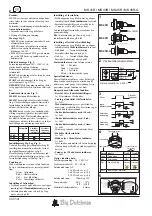
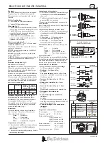
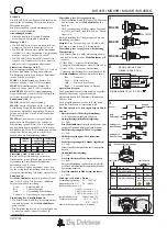
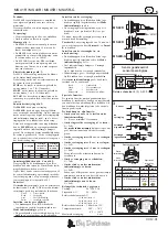
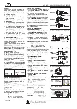
Mounting fig. 1:
• The MS 40R series should be installed so that at
least 10 mm of the sensor contact point is free.
• The MS 40R series in a smooth design is
mounted efficiently in a special gland, addi-
tional accessories no. 140107.
• The MS 40R-G series with M30 thread is
mounted in a hole diameter 30 mm, and is
tightened with a locknut.
Electric mounting fig. 2:
The power supply 90V - 250V AC is connected
to the blue and brown wire.
The load is connected in series with the relay
contact of the sensor.
STOP by activating the sensor, use the black
wires 1 and 3 (NC).
START by activating the sensor, use the black
wires 1 and 4 (NO).
NOTICE! With the power supply connected and
a non-activated sensor the internal relay is
pulled.
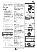
Function description fig. 3:
MS 41R has no time-delay.
MS 43R has an option for delayed switch-off.
When the activation stops, the time-delay
begins (red flash), and when this delay has run
out, the relay switches back.
Besides the two options above the MS 45R can
also be set for delayed switch-on (green flash).
The time-delay will start immediately when the
sensor is activated. When the delay period runs
out, the relay will switch, and not switch back
until the activation stops.
Sensitivity
Delayed
Delayed
switch-off
switch-on
( Off delay )
( On delay )
MS 41R
MS 43R
MS 45R
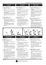
Options of adjustment fig. 4 and fig. 5:
By activating both the switches A and B si-
multaneously, you can switch between the dif-
ferent options of adjustments, see fig 4.
It is marked on the label if the sensor is adjusted
for delayed switch-on (on-delay), or delayed
switch-off (off-delay), fig. 5.
Functions:
The mode indicator shows the selected func-
tion. See fig. 4. The colour of the indicator
shows the selected function:
Green
=
Sensitivity.
Red
=
Time-delay.
Yellow =
Switch on/off.
Black
=
Adjustments completed.
Adjustment of sensitivity:
• The switches A and B are activated and let go
simultaneously until the Mode indicator
shows green.
• The sensitivity is reduced by pressing A and is
increased by pressing B.
Adjustment of time-delay:
• The switches A and B are activated and let go
simultaneously until the Mode indicator
shows red.
• The delay is adjusted by pressing A (1 min. per
press) and B (1 sec. per press).
The new time-delay adjustment overwrites the
old adjustment.
Ex.: A delay of 10 min. and 5 sec. is adjusted with
10 x A and 5 x B.
Adjustment of delayed switch-off/on:
• The switches A and B are activated and let go
simultaneously until the Mode indicator
shows yellow.
• Yellow flash =
Delayed switch-on.
Delayed switch-on by pressing A.
• Yellow light
=
Delayed switch-off.
Delayed switch-off by pressing B.
The status indicator shows the status of the
sensor.
Red
=
Activated
Green
=
Not activated
Yellow =
Defect in the sensor
Flash
=
Time-delay in progress
Special functions:
Special functions are accomplished by holding
button A down and simultaneously pressing but-
ton B a number of times. When you let go of
button A, the special function is in operation.
The switch and its function:
• Reset of sensor (factory presetting):
A + B for minimum 15 seconds.
• Reading of set time-delay:
A + 2xB:
The mode indicator emits a yellow flash
every hour, a red flash every minute a green
flash every second.
• Increase the time-delay by +10 sec.:
A + 4xB.
• Reduce the time-delay by -5 sec.:
A + 5xB.
• Increase the time-delay by +1 hour:
A + 6xB.
Minutes and seconds must be entered first.
• Disconnect the time-delay:
A + 7xB.
• Turn off the light in mode/status
indicator:
A + 8xB.
The light is turned on automatically by the
first press on either A or B and is turned off
again after a short while.
• Turn on the light in the mode/status
indicator:
A + 9xB.
Important technical data:
Power supply:
90 - 250V AC
Frequency area AC:
50 - 60 Hz
Relay switch max AC:
1,1 kVA at cos
ϕ
= 1
1,0 kVA at cos
ϕ
= 0,8
0,7 kVA at cos
ϕ
= 0,4
Relay switch min.:
100 mA and 12V
Temperature area:
-20°C - + 70°C
-4°F - +158°F
Maximum time-delay:
4 hours
MS 40R
MS 40R
MS 40R-G


