background image

HLDA 

– Double acting - Doubled thrust hydraulic linear actuator  

Use and maintenance manual 

© Copyright by BIFFI Italia. All right reserved.


Pag. 32 


Contents may change without notice


3) Unscrew  the  stop  screw  (19)  by  turning  it  anticlockwise  with  an 

Allen wrench until the screw is complete with drawn inside the end 
flange threaded hole. 

4) Unscrew  the  nuts  (20)  from  the  tie  rods  (18):  they  must  be 

gradually unscrewed all at the same time. 

5) Slide off the end flange (13) and the tube (16). 

6) If  the  actuator  control  unit  requires  the  cylinder  chamber  head 

flange side to be also filled with oil, and the piston rod seal ring (3) 
to be replaced, remove the screw (2) and the flange (1). Unscrew 
the piston rod (15) threaded end from the adaptor bush.  Slide off 
the piston rod (15) from the head flange (1). 

7) Disassemble the head flange. 

Seals replacement 

Prior to reassembly check that the actuator components are in good 
conditions  and  clean.  Lubricate  all  the  surfaces  of  the  parts,  which 
move in contact with other components, by a recommended grease. 
If  the  O-ring  must  be  replaced,  remove  the  existing  one  from  its 
groove, clean the groove carefully and lubricate it with a protective oil 
or grease film. Assemble the new O-ring into its groove and lubricate 
it with a protective oil or grease film. 

1) Replace the O-ring (5) of the head flange (1). 

2) Replace the back-up-ring (4) of the end flange (13). 

3) Replace the scraper-ring (33) into the flange (32) placed under the 

head flange 

To replace the piston rod seal rings (3) proceed as follows : 

1) Remove the existing seal ring (3) with its O-ring from their groove. 

2) Clean  the  groove  carefully  and  lubricate  it  with  a  protective  oil  or 

grease film. 

3) Assemble  the  new  O-ring  into  its  groove  and  lubricate  it  with  a 

protective oil or grease film. 

4) Assemble  the  new  seal  ring  (3)  into  the  flange  groove,  inside  its 

rubber O-ring, by bending it : take care that the bending radius is 
as large as possible to avoid damaged the seal. Then enlarge the 
seal  ring  with  your  fingers  so  as  to  restore  its  round  shape:  pay 
attention not to utilise any tools which can damage the seal ring. 

To replace the piston seal ring (7) proceed as follows : 

1) Remove the existing seal ring (7) with its O-ring from their groove. 

2) Clean  the  groove  carefully  and  lubricate  it  with  a  protective  oil  or 

grease film. 

Содержание HLDA

Страница 1: ...Contents may change without notice MAN 668 Use and maintenance manual HLDA DOUBLED THRUST DOUBLE ACTING HYDRAULIC LINEAR ACTUATOR 2 23 05 18 Updated data plate Ermanni Orefici Vigliano 1 30 03 17 Upd...

Страница 2: ...n and use 17 3 1 OPERATION DESCRIPTION 17 3 2 RESIDUAL RISKS 18 3 3 OPERATIONS 18 refer to specific document BIFFI operating diagram furnished 18 3 3 1Emergency manual operation MHP 18 3 3 2Remote con...

Страница 3: ...S r l pays the highest attention to collecting and verifying the documentation contained in this user manual However BIFFI Italia S r l is not liable for any mistakes contained in this manual for dam...

Страница 4: ...nd safety instructions for use in hazardous area 1 1 2 Terms and conditions Biffi Italia srl guarantees that all the items produced are free of defects in workmanship and manufacturing materials and m...

Страница 5: ...THE ACTUATOR HLDA double acting doubled thrust hydraulic linear actuators are suitable to operate the kind of linear valves with rising stem or requiring a high thrust value in the first phase of valv...

Страница 6: ...raulic linear actuator Use and maintenance manual Copyright by BIFFI Italia All right reserved Pag 6 Contents may change without notice When the double piston has completed the stroke the remaining st...

Страница 7: ...the emergency strokes The linear stroke of the valve is adjustable by means of the external mechanical stop for upward position and by the adjustment of the coupling of valve stem to actuator joint f...

Страница 8: ...Check that the actuator was not damaged during transportation if necessary renovate the painting according to the specification reported on the order confirmation If the actuator is received already...

Страница 9: ...fied staff and in compliance with the laws and provisions in force The fastening points are appropriate for the lifting of the actuator alone and not for the valve actuator assembly Avoid that during...

Страница 10: ...installation follow these steps Place it on a wood surface in order not to deteriorate the area of valve coupling Make sure that plastic plugs are present on the hydraulic and electrical connections i...

Страница 11: ...ical position see picture 1 For handling transporting and assembling the actuator in horizontal position by safety hook for chains use the lifting points on the top of cylinder head flange and on coup...

Страница 12: ...tion Note the eyebolt is sized for the lifting of the only actuator NOT ACTUATOR VALVE Proper lifting points have to be foreseen for the valve 3 Screw the actuator coupling joint onto the valve by rot...

Страница 13: ...make easier the assembly the valve stem has to be in perfect vertical position 3 Disassemble the two halves of actuator pedestal shell joint item 8 by unscrewing the retaining screws item 4 therefore...

Страница 14: ...ning torque Nm M8 20 M10 40 M12 70 M14 110 M16 160 M20 320 M22 420 M24 550 M27 800 M30 1100 M33 1400 M36 1700 The screwing values in Table 1 were calculated considering the materials ASTM A320 L7 for...

Страница 15: ...s If necessary tighten the nuts of the pipe fittings 2 6 ELECTRICAL CONNECTIONS IF ANY Use components appropriate as for type material and dimensions The connections should be made by qualified staff...

Страница 16: ...tches pressure switches etc are compatible with those reported on the identification plate of the actuator Figure 1 Check that the setting of the components of the actuator control unit pressure regul...

Страница 17: ...c cylinder chamber relevant to the operation to carry out opening or closing see following pages This pressure starts the linear motion of the piston and the consequent motion of the valve stem that i...

Страница 18: ...HLA actuators can have an emergency manual override in addition to the local and or remote control system which controls the oil supplied by a power pack for the normal actuator operation The emergenc...

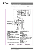
Страница 19: ...hydraulic linear actuator Use and maintenance manual Copyright by BIFFI Italia All right reserved Pag 19 Contents may change without notice Example of operating diagram for Double acting hydraulic li...

Страница 20: ...st hydraulic linear actuator Use and maintenance manual Copyright by BIFFI Italia All right reserved Pag 20 Contents may change without notice Example of operating diagram for Double acting hydraulic...

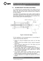
Страница 21: ...Figure 5 Mechanical stopper For the adjustment of the mechanical stop on the end flange of cylinder follow these steps Figure 6 Remove by using an hexagonal open wrench c1 the lifting eyebolt Unscrew...

Страница 22: ...otice For high pressure cylinder models the mechanical stop is internal without protection cover proceed at the same way 1 remove the plug and 2 operate the adjusting screw Figure 6 Mechanical stopper...

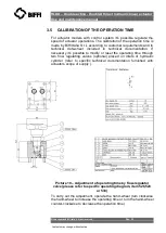
Страница 23: ...he relative wiring diagram and follow these steps Unscrew the fastening screws of the cover Picture 7 Remove the cover paying attention not to deteriorate the gasket and the cylindrical and flat coupl...

Страница 24: ...on of the valve but is turned by 90 Remove the roll pin placed on the position indicator index Turn the indicator until reaching its proper positioning Put the roll pin back in its position End of str...

Страница 25: ...ts and to technical data sheet included in technical documentation If necessary it s possible to modify or reset the operating time through two flow regulating valves optional placed on inlets of hydr...

Страница 26: ...ht by BIFFI Italia All right reserved Pag 26 Contents may change without notice 4 Operational tests and inspections Important To ensure the guaranteed SIL grade according to IEC 61508 the functionalit...

Страница 27: ...nyway every 2 years of operation the following is recommended Check that the actuator operates the valve correctly and with the required operating times If the actuator operation is very infrequent ca...

Страница 28: ...into the tank 4 is in correspondence of the MAX LEVEL notch of the dipstick 4 By leaving the dipstick unscrewed move the actuator by the pneumatic control or by the hand pump to closed position 5 Scre...

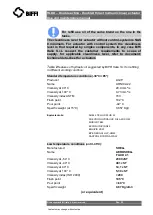
Страница 29: ...able 2 features of hydraulic oil suggested by BIFFI Italia S r l for refilling in different working condition Standard temperature conditions 30 C 85 Producer AGIP Name ARNICA 22 Viscosity at 40 C 20...

Страница 30: ...case of need extraordinary maintenance can be performed on the parts of the actuator Anyway contact BIFFI ITALIA customer care 5 2 1 Lubrication of mechanism For normal duty the HLDA actuator is lubr...

Страница 31: ...5 C COC Based on synthetic oil Dropping point 260 C ASTM D 566 Product code 001A0065 Infosafe No ACISO GB eng C If there are leaks in the hydraulic cylinder or a malfunction in the mechanical componen...

Страница 32: ...e replaced remove the existing one from its groove clean the groove carefully and lubricate it with a protective oil or grease film Assemble the new O ring into its groove and lubricate it with a prot...

Страница 33: ...nd of the piston rod 15 and the threaded hole of the adaptor Spread some sealant LOCTITE 452 or equivalent on the rod threaded end and tighten 3 Carefully clean the inside of the tube 14 and check tha...

Страница 34: ...ng Doubled thrust hydraulic linear actuator Use and maintenance manual Copyright by BIFFI Italia All right reserved Pag 34 Contents may change without notice DOUBLE ACTING HYDRAULIC LINEAR ACTUATOR SE...

Страница 35: ...the cylinder of the actuator from the control unit and from the accumulator tank if present If actuator is still mounted onto the valve loosen the threaded connections between valve and actuator scre...

Страница 36: ...ong calibration of flow regulator valves Restore Sect 3 6 Wear of the valve Replace Actuator too fast High supply pressure Restore Sect 1 4 Wrong calibration of flow regulator valves Restore Sect 3 6...

Страница 37: ...reference to BIFFI order confirmation concerning all the supply and serial number of the actuator Sect 1 2 for any specific spare part for a specific actuator model Please send every spare parts requ...

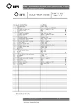
Страница 38: ...hydraulic linear actuator Use and maintenance manual Copyright by BIFFI Italia All right reserved Pag 38 Contents may change without notice 7 2 PARTS LIST FOR MAINTENANCE AND REPLACING PROCEDURE Tabl...

Страница 39: ...HLDA Double acting Doubled thrust hydraulic linear actuator Use and maintenance manual Copyright by BIFFI Italia All right reserved Pag 39 Contents may change without notice Table 2 hydraulic cylinder...

Страница 40: ...HLDA Double acting Doubled thrust hydraulic linear actuator Use and maintenance manual Copyright by BIFFI Italia All right reserved Pag 40 Contents may change without notice...

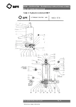
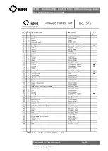
Страница 41: ...Double acting Doubled thrust hydraulic linear actuator Use and maintenance manual Copyright by BIFFI Italia All right reserved Pag 41 Contents may change without notice Table 3 Hydraulic control unit...

Страница 42: ...HLDA Double acting Doubled thrust hydraulic linear actuator Use and maintenance manual Copyright by BIFFI Italia All right reserved Pag 42 Contents may change without notice...

Страница 43: ...HLDA Double acting Doubled thrust hydraulic linear actuator Use and maintenance manual Copyright by BIFFI Italia All right reserved Pag 43 Contents may change without notice...

Страница 44: ...y BIFFI Italia All right reserved Pag 44 Contents may change without notice 8 Date report for maintenance operations Last maintenance operation date in factory on delivery exec by exec by exec by Next...

Отзывы: