


HLDA
– Double acting - Doubled thrust hydraulic linear actuator
Use and maintenance manual
© Copyright by BIFFI Italia. All right reserved.
Pag. 11
Contents may change without notice
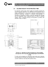
2.4
ACTUATOR ASSEMBLY ON THE VALVE
2.4.1 Types of assembly
The adapter pedestal in fabricated carbon steel is specifically
designed for adaptation to any type of valve with provision for local
indicator, limit switches and other accessories (on request).
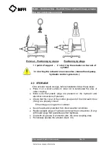
Lift the actuator by safety-hook for chains using the lifting-points (see
sect. 2.2) on the top of actuator for handling, transporting and
assembling in vertical position (see picture 1).
For handling,
transporting and assembling the actuator in horizontal position by
safety-hook for chains use the lifting-points on the top of cylinder
head-flange and on coupling flange (see picture 2).
2.4.2 Assembly procedure
Failure to comply with the following procedures may
impair product warranty. Installation, commissioning
and maintenance and repair works should be carried
out by qualified staff.
A non-conforming assembly could be the source of
serious accidents.
For actuator assembly on the valve:
Check that the assembly position, as shown on the
d
ocumentation, complies with system’s geometry.
Check the consistency of the parts of actuator-valve
coupling.
A) TO ASSEMBLE THE ACTUATOR ONTO THE VALVE BY BRACKET
WITH THREADED JOINT PROCEED AS FOLLOWS: