HLDA
– Double acting - Doubled thrust hydraulic linear actuator
Use and maintenance manual
© Copyright by BIFFI Italia. All right reserved.
Pag. 23
Contents may change without notice
3.5 CALIBRATION OF MICROSWITCHES (BIFFI LIMIT
SWITCH BOX ONLY)
Operate only the micro-switch corresponding to the
direction of operation being carried out, as clearly
reported on the micro-switch.
If different micro-switches assembly or limit switch box is
supplied, please refer to the specific documentation.
Micro-switches are placed inside a special box (Picture 7).
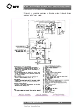
For micro-switches calibration please refer to the relative wiring
diagram and follow these steps:
❑
Unscrew the fastening screws of the cover (Picture 7).
❑
Remove the cover paying attention not to deteriorate the gasket
and the cylindrical and flat coupling surfaces.
❑
Operate the actuator (in opening or closing) with local hydraulic
operation (Section 3.3)
❑
Unscrew the screw of the operating cam relative to the micro-
switch to calibrate and adjust it according to the settings (Picture
8).
❑
Tighten the screw.
❑
Operate the actuator and adjust any other micro-switch with the
procedure already described.
❑
Position the cover making sure the cam-carrier shaft grips with
the index dragging shaft.
❑
Check that the cover and the index show the proper position of
the valve (Picture 9).
❑
Tighten the screws.
Picture 7
– Micro-switches
box
Picture 8
– Cam adjustment


