


Gas conversion
39
number of times corresponding to the setting of
the knob 9 in Fig. 8.5.
NATURAL
4
L.P.G.
9
Gas type
Setting No.
GAS
1
Fig. 8.5
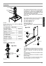
Gas
supply
Position of
knob 9
Approx. Max current
through the modulator
device
Natural
gas
1
125 mA
L.P.G.
4
165 mA
Fig. 8.6
13 To change the setting turn the knob 9 on a posi-
tion corresponding to the gas used as shown
in Fig. 8.5.
By turning the knob 9, the lock---out signal
lamp 6 blinks quickly (2 per seconds) indicat-
ing that the setting has changed and must be
memorised.
14 To memorize the setting keep pressed the
reset button 7 for about 5 seconds until the
lamps 10 briefly blinks simultaneously.
15 Open the gas cock (14 in Fig. 8.7)
Open position
14
Fig. 8.7
16 To reset the boiler to the normal operation turn
it ON by the function selector 8 on the desired
operation and checking the ignition pressure
and that the burner lights up uniformly. In any
case, the boiler automatically resets to its nor-
mal operation after 10 minutes.
Factory setting = Natural gas (as illustrated)
17 Calibrate the gas valve according to the in-
structions given in the service manual, section
Modulating gas valve --- Adjustment
.
18 Re---assemble the lid of the sealed chamber.
19 Replace the self---adhesive label indicating the
type of gas, and the gas pressures to which the
appliance has been set with the label included
with the conversion kit. The label is placed on
the botton of the appliance.
20 Replace the adjustment protection cap.
21 Replace the front panels of the case.
M
A
IN
TE
NA
NCE