


Installation
28
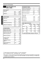
6.4
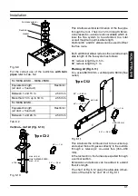
Overall dimensions
ø80
ø80
ø100
400
200
47
245
196
803 700
35
115
142
16
31
60
60
100
257
200
65
64
52
65
50
73
350
198
A, B and C
Boiler
fron
t
B
A
C
Gas
D.h.w.
C.h.
Cold
C.h.
return
flow
outlet
water
inlet
Electric
connection
area
A --- air intake/flue outlet pipe (co---axial)
B --- flue outlet pipe ø 80 mm (twin kit)
C --- air intake pipe ø 80 mm (twin kit)
Condensate drain
connection
area
Fig. 6.2 (all dimensions in mm)
6.5
Joints
Functions
Pipe sizes (o.d)
Gas, c.h. return, c.h. flow
ø 22
D.c.w. inlet
ø 15
D.h.w. outlet
ø 15
Pressure relief valve
ø 15
Condensate drain
ø 25 (plastic)
Tab. 6.1 (sizes in mm o.d.)
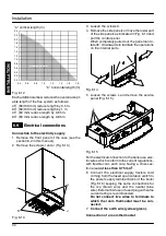
6.6
Mounting the boiler
1 Take the protective caps off the boiler pipe-
work.
2 Thoroughly clean the connections.
3 Mount the boiler on its bracket.
4 Fix the c.h. valves A and gas cock B (¾”) to the
boiler using the ¾” gaskets (Fig. 6.3)
5 Fix the ø 22 mm pipes C (c.h. circuit) to the c.h.
valves A and the ø 22 mm pipe D (gas) to the
cock B using the ¾” gaskets.
6 Repeat the above procedure for the d.c.w. inlet
utilising the ½” cold water inlet valve E, the ø 15
mm copper tail F with its connection nut and
two ½” gaskets.
7 Fix the ø 15 mm copper tail G with the ½” con-
nection nut and a ½” gasket.
C
A
A
B
D
C
E
F
G
Fig. 6.3
8 Connect the pipe H (Fig. 6.4) from the pres-
sure relief valve to the safety discharge pipe-
work.
9 Fit the condensate drain 11 (Fig. 6.4) in the air
brake connected to the drainage pipework.
See also section 5.7 in this manual.
IN
S
TA
LLA
TI
O
N