


Installation
31
Air intake adapter
Restrictor
Gasket
Fig. 6.9
For the correct use of the restrictors
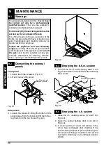
with twin
pipes
refer to Tab. 6.2.
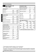
For M96A.24SM/..., M96A.28SM/...
Equivalent length
(air duct + flue duct)
Restrictor
Between 1 and 15 m
ø 50 mm
More than 15 m up to 30 m
ø 55 mm
For M96A.32SM/...
Equivalent length
(air duct + flue duct)
Restrictor
Between 1 and 24 m
ø 50 mm
Tab. 6.2
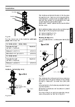
Vertical--- roof kit (Fig. 6.10)
90
˚
=--- 1 m
45
˚
=--- 0,5 m
max =8,5 m
Only for M96A.32SM/...
max = 6 m
ø 125
Type C32
Fig. 6.10
This kit allows vertical termination of the flue pipe
through the roof. The kit is 1.2 m in length. Exten-
sion pieces (Co---axial) are also available which al-
lows the flue system to be extended to a total
overall maximum permissible length.
Optional 45
˚
and 90
˚
elbows can be used to offset
the flue route.
Each additional elbow reduces the overall accept-
able length of the flue system as follows:
45
˚
reduce length by 0,5 m.
90
˚
reduce length by 1 m.
Pluming kit (Fig. 6.11)
Co---axial ø 60/100mm + vertical part ø 60mm (flue
outlet)
90
˚
=--- 1 m
45
˚
=--- 0,5 m
90
˚
=--- 0,85 m
45
˚
=--- 0,65 m
ø 60 mm
ø 60/100 mm
Type C52
Fig. 6.11
This kit allows the comburent air to be sucked up
and expel the burnt gasses directly to the outside
through a telescopic co---axial flue (450---950
mm).
In the last section, the fumes are expelled through
a vertical section.
Extensions and elbows can be added to extend
the kit’s length.
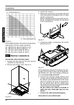
The chart of Fig. 6.12 gives the allowable dimen-
sions of the ducts “
a
” and “
b
” of Fig. 6.11
IN
S
TA
LLA
TI
O
N