background image


MOD. H720BM 


9

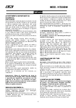
5. FITTING THE BOTTLE HOLDER.- 

Release  the  screws  (93)  on  the  handlebar  (17), 

position  the  bottle  holder  and  adaptor  (92)  lower  the 

cover  (61)    and  secure  it  by  using  the  screws  (93) 

removed previously. 


6. INSTRUCTIONS FOR FITTING THE 

SADDLE.- 

Take the horizontal tube for the saddle (23) and attach 

the saddle (74) to it, Fig.6, tighten the nuts (Z).  


VERTICAL ADJUSTMENT

In order to raise or lower the saddle post, first loosen 

off the control knob (91) on the saddle post a little by 

turning it in an anticlockwise direction, pull the control 

knob  back  and  without  releasing  it,  move  the  saddle 

post up  or  down, Fig.6. When it is at the right height 

release  the  knob  and  it  will  lock  into  a  hole  on  the 

saddle post. Tighten it up by turning the control knob 

(91) in a clockwise direction. 


HORIZONTAL ADJUSTMENT

.  

To  adjust  the  saddle’s  horizontal  position,  loosen  the 

control knob on the saddle’s horizontal bar and move 

the  saddle,  along  with  the  bar,  into  the  desired 

position, then tighten the control knob securely, Fig.6. 


TILTING THE SADDLE. 

The saddle can be tilted backward or forward. Loosen 

off  nut  (Z)  shown  in  Fig.6,  located  under  the  saddle, 

tilt  the  saddle  into  the  desired  position  and  then 

retighten the nut securely. 


Do  not  adjust  the  tilt  of  the  saddle  while  you  are 
still sitting on it. 


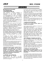
7. FITTING THE MONITOR.-


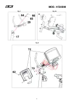
Fit  the  handlebar  (29)  onto  the  handlebar  stem  (17) 

with the screws (66) and washers (64) and (65) Fig. 7. 

Tighten the two pre-assembled screws located on the 

front of the mast to secure the handlebar position. Fig 

7A. 

Tighten the two pre-assembled screws located on the 

front of the mast to secure the handlebar position. Fig 

7A. 

Bring  the  monitor  (72)  to  the  handlebar  stem  (17) 

Fig.8,  connect  the  terminals  coming  out  of  the 

handlebar stem (17) and the monitor (72).  

Insert the monitor (72) onto the  handlebar stem (17), 

as shown in Fig.8, making sure not to pinch any of the 

cables. 

Fit  the  bolts  (73),  making  sure  that  the  handlebar  is 

aligned correctly, securely tighten all of the bolts on the 

handlebar  stem  including  the  bolts  at  the  base  which 

were left hand tight in point 4. Insert the 2 metal sheets 

(99) and fix them with screws (73) Fig.8A. 

Take  the  monitor  covers,  Fig.8.  Now  use  the  screws 

(62) to  attach  them to  the  post  and  the cover (61)  with 

screws (89). 


LEVELLING.- 

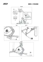
Once  the  unit  has  been  placed  into  its  final  position, 

make  sure  that  it  sits  flat  on  the  floor  and  that  it  is 

level. This is achieved by screwing the adjustable foot 

(34) up or down, Fig.9. 


MOVEMENT & STORAGE

.- 

The  unit  is  equipped  with  wheels  (38)  to  make  it 

easier to move about. The two  wheels at the front  of 

the unit make it easier to place the unit in any chosen 

position,  as  shown  in  the  Fig.10.  Store  it  in  a  dry 

place,  preferably  not  subject  to  changes  in 

temperature. 


MAINS CONNECTION.- 

Insert  the  jack  (m)  on  the  transformer  (75)  into  the 

connection hole on the main body (1) (bottom, rear of 

the machine) and then plug the transformer into a 220 

V mains supply, Fig.11. 


Do  not  hesitate  to  get  touch  with  the  Technical 

Assistance  Service  if  you  have  any  queries  by 

phoning customer services (see last page in manual). 


BH  RESERVES  THE  RIGHT  TO  MODIFY  THE 
SPECIFICATIONS  OF  ITS  PRODUCTS  WITHOUT 
PRIOR NOTICE


Содержание H720BM

Страница 1: ... de montaje y utilización Instructions for assembly and use Instructions de montage et utilisation Montage und gebrauchsanleitung Instruções de montagem e utilização Istruzioni di montaggio e uso Montage en gebruiksinstrukties ...

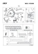
Страница 2: ...MOD H720BM 2 Fig 1 ...

Страница 3: ...MOD H720BM 3 Fig 2 Fig 3 Fig 4 Fig 5 Fig 6 ...

Страница 4: ...MOD H720BM 4 Fig 7 Fig 7A Fig 8 ...

Страница 5: ...MOD H720BM 5 Fig 8A Fig 9 Fig 10 Fig 11 ...

Страница 6: ...a uso profesional Peso máximo del usuario 180kg El frenado es independiente de la velocidad 2 Los padres y otras personas responsables de los niños deben de tener en cuenta la naturaleza curiosa de estos y que puede llevarles a situaciones y conductas que pueden resultar peligrosas Esta unidad no ha de utilizarse en ningún caso como juguete 3 Es responsabilidad del propietario asegurarse que todos...

Страница 7: ...r 29 en el alojamiento del tubo 17 con los tornillos 66 y arandelas planas 64 y arandelas elásticas 65 Fig 7 Apriete los dos tornillos premontados situados en la parte frontal del mástil para fijar la posición del manillar Fig 7A Acerque el monitor 72 al tubo manillar 29 Fig 8 conexione los terminales que salen del tubo manillar 17 y del monitor 72 Fig 8 Introduzca el monitor 72 en el manillar 17 ...

Страница 8: ...ccount and how this can often lead to hazardous situations and behaviour resulting in accidents Under no circumstances should this appliance be used as a toy 3 The owner is responsible for ensuring that anyone who uses the machine is duly informed about the necessary precautions 1 ASSEMBLY INSTRUCTIONS Take the unit out of its box and make sure that all of the pieces are there Fig 1 The assistance...

Страница 9: ...to secure the handlebar position Fig 7A Tighten the two pre assembled screws located on the front of the mast to secure the handlebar position Fig 7A Bring the monitor 72 to the handlebar stem 17 Fig 8 connect the terminals coming out of the handlebar stem 17 and the monitor 72 Insert the monitor 72 onto the handlebar stem 17 as shown in Fig 8 making sure not to pinch any of the cables Fit the bol...

Страница 10: ... informations sur le montage la sécurité et l utilisation de la machine 1 Cet appareil a fait l objet de tests et répond à la norme EN957 et convient à l usage professionnel Poids maximum de l utilisateur 180kg 2 Les parents ou personnes à qui des enfants ont été confi és doivent tenir compte de leur soif de curiosité qui peut les conduire à avoir des conduites risquant de se traduire par des situ...

Страница 11: ...CE DU MONITEUR Placer le guidon 29 dans le tube de boîtier 17 avec des vis 66 et les rondelles plates 65 et des rondelles élastiques 64 Fig 7 Serrer les deux vis pré montés à l avant du mât pour fixer la position de manillar Fig 7A Approchez le moniteur 72 au tube guidon 29 Fig 8 connectez les bornes qui dépassent du tube guidon 17 et du moniteur 72 Fig 8 Introduisez le moniteur 72 dans le tube gu...

Страница 12: ...de getestet und erfüllt die Anforderungen der Norm EN957 für professionelle Anwendung Maximales Benutzergewicht 180 kg Die Bremswirkung ist unabhängig von der Geschwindigkeit 2 Eltern bzw Aufsichtspflichtige von Kindern sollten deren natürliche Neugier berücksichtigen die u U gefährliche Situationen und Verhaltensweisen mit sich bringen kann Dieses Gerät darf unter keinen Umständen als Spielzeug v...

Страница 13: ...erohr 17 mit Schrauben 66 und Unterlegscheiben 65 und Federringen 64 Fig 7 Ziehen Sie die beiden Schrauben an der Vorderseite des Mastes vormontiert die Position von manillar Fig 7A zu beheben Führen Sie den Monitor 72 an die Lenkerstange 17 Fig 8 und verbinden Sie die Klemmen die aus der Lenkerstange 17 und dem Monitor 72 kommen Fig 8 Setzen Sie den Monitor 72 auf die Lenkerstange 17 Fig 8 achten...

Страница 14: ...a 1 Este aparelho foi testado e cumpre com a norma EN957 adecuado para uso profissional Peso máximo do utilizador 180kg A travagem é independente da velocidade 2 Os pais e outras pessoas responsáveis por crianças deverão ter em conta ua natureza curiosa que poderá levá las a situações e comportamentos que podem er perigosos Este aparelho nunca deverá utilizar se como um brinquedo 3 É responsabilid...

Страница 15: ...O MONITOR Coloque o guiador 29 no tubo da caixa 17 com os parafusos 66 e arruelas 65 e arruelas 64 Fig 7 Apertar os dois parafusos de pré montado na parte frontal do mastro para fixar a posição de manillar Fig 7A Aproxime o monitor 72 ao tubo guiador 29 Fig 8 Ligue os dois terminais que aem do tubo guiador 17 e do monitor 72 Fig 8 Introduza o monitor 72 no tubo guiador 17 como indica a Fig 8 tendo...

Страница 16: ... è stato testato ed è a norma con il EN957 adeguato per l uso professionale Peso massimo dell utente 180 kg 2 I genitori ed altre persone resoponsabili del bambini devono tenere conto della natura curiosa di questi che li può portare a situazioni e condotto che possono risultare pericolose Questo apparecchio non si deve usare in nessun caso come un giocattolo 3 È responsabilità del proprietario l ...

Страница 17: ...e il manubrio 29 nel tubo di alloggiamento 17 con le viti 66 e le rondelle 65 e le rondelle 64 Fig 7 Serrare le due viti pre montati sulla parte anteriore dell albero per fissare la posizione di manillar Fig 7A Avvicini il monitor 72 al tubo manubrio 29 Fig 8 colleghi i due terminali che fuoriescono dal tubo manubrio 17 e dal monitor 72 Fig 8 Introduca il monitor 72 nel tubo del manubrio 17 como i...

Страница 18: ...JZINGEN Lees zorgvuldig de instructies in deze gebruiksaanwijzing Deze geeft u belangrijke aanwijzingen over de montage veiligheid en het gebruik van het apparaat 1 Dit toestel is getest en het voldoet aan de EN957 norm geschikt voor professioneel gebruik Maximaal gewicht gebruiker 180kg Er kan geremd worden onafhankelijk van snelheid 2 Ouders en andere personen die verantwoordelijk zijn voor kind...

Страница 19: ...ING VAN DE MONITOR Zet de framebuis 29 in de behuizing buis 17 met schroeven 66 en sluitringen 65 en veerringen 64 Fig 7 Draai de twee schroeven vooraf aan de voorzijde van de mast om de positie van manillar Fig 7A lossen Breng de monitor 72 naar de framebuis 29 Fig 8 verbind de terminals die uit de framebuis 17 steken met die van de monitor 72 Fig 8 Plaats de monitor 72 op de framebuis 29 zoals w...

Страница 20: ...MOD H720BM 20 H720BM ...

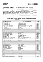
Страница 21: ...st welding Tija sillín H720BM020N 21 Quick released knob Pomo rápido H720BM021N 23 Seat sliding weldment Deslizadera sillín H720023 29 handlebar with dipping Manillar H720BM029 30 Hand pulse set 900mm Conjunto pulso H862030 31 Front stabilizer set Set caballete delantero H720031 33 stabilizer cap Taco del caballete H720033 34 Adjusting pad of front stabilizer Tacos ajustables del caballete delante...

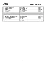
Страница 22: ...086 88 Belt J8 450 Correa J8 450 H720088 90 Crank right Biela derecha H720090B 91 Quick released knob Pomo H720091 92 Bottle holder adaptor Adaptador portabotellín H720092 93 RJ45 internet cable middle 1200mm Cable internet medio H720BM093 94 Lower console cable 850mm Cable cuadro H720094 95 power wire 900mm Cable DC H720095 97 Bottle holder Portabotellines H720097 100 Pedal belt Correa pedal H720...

Страница 23: ...E et 2014 35 CE Deutsch Hiermit erklärt Exercycle S L dass sich das Gerät in Übereinstimmung mit den grundlegenden Anforderungen und den übrigen einschlägigen Bestimmungen der Richtlinien 2009 125 EG 2011 65 EG 2014 30 EG und 2014 35 EG befindet Português Exercycle S L declara que este producto está conforme com os requisitos essenciais e outras disposições das Directivas 2009 125 CE 2011 65 CE 20...

Страница 24: ...BH HIPOWER CHINA BH China Co Ltd Block A NO 68 Branch Lane 455 Lane 822 Zhen Nan RD Li Zi Yuan Putuo Shanghai 200331 P R C Tel 86 021 5284 6694 Fax 86 021 5284 6814 e mail info i bh cn BH HIPOWER UK Tel 02037347554 e mail sales uk bhfitness com AFTER SALES UK Tel 02074425525 e mail service uk bhfitness com BH HIPOWER FRANCE SAV FRANCE Tel 33 0810 000 301 Fax 33 0810 000 290 savfrance bhfitness com...

Отзывы: