BEST ACCESS SYSTEMS
Indianapolis, Indiana
For factory prepared doors only
Caution:
If you use hollow metal doors, determine whether the
doors are reinforced enough to support the lock. If door rein-
forcement is not adequate, consult the door manufacturer for
information on proper reinforcement.
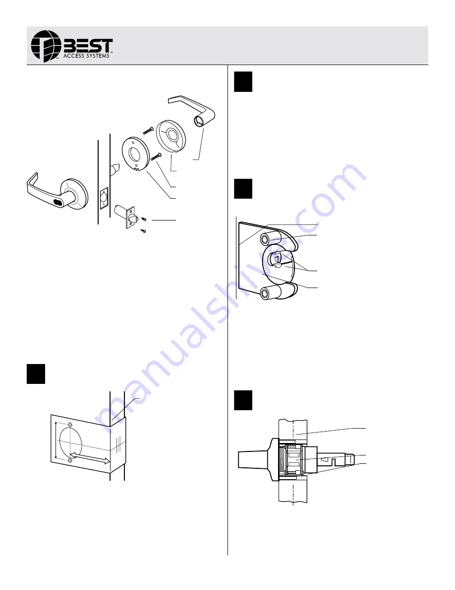
Simplified instructions
1 Install the latch so that the bevel on the latchbolt faces the strike.
2 Adjust the outside rose assembly so that the chassis is centered in
the door. Install the chassis from the outside of the door.
3 Install the inside liner, through-bolts, rose, lever and strike.
For field door preparation and detailed installation instructions, see the
following tasks.
1
Position template
1 Fold the template and place it in position on the high edge of the
door bevel. See Figure 2.
2 Mark the drill points.
Note:
The suggested height from the floor to centerline of the lock is
40 5/16". If steel frames are used, the latch centerline must be in line
with the center of the strike preparation.
2
Bore two holes and install latch
1 Bore a 2 1/8" diameter hole from both sides of the door, to the center
of the door.
2 Drill a 1" diameter hole from the edge of the door that intersects the
2 1/8" hole.
3 Mortise the door edge for the latch face.
4 Install the latch through the 1” diameter hole. For drive-in latches,
use a rubber mallet. Latch tabs should project into the 2 1/8"
diameter hole. See figure 3 in task 3.
5 Check the door swing.
3
Install boring jig and drill two
5/16
”
diameter holes
1 Install the boring jig onto the door and engage with the latch tabs.
Make sure the front edge of the jig is parallel with the door edge. See
Figure 3.
2 Drill two 5/16" diameter holes halfway into the door.
3 Turn the boring jig over and repeat steps one and two from the
opposite side of the door.
Note:
Replace the boring jig after ten door preparations.
4
Adjust lock to door thickness
1 Temporarily remove the latch.
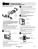
Figure 1 — Overview of installing the lock
Figure 2 — Placing the template onto the door
Inside rose
Inside liner
Latch
Through-bolts
Outside
Lever
TEMPLATE
High edge of door bevel
Figure 3 — Installing the boring jig onto the door
Figure 4 — Adjusting the lock to match the door thickness
Door edge
5/16” diameter
Latch tabs
Boring jig
Door center
Retractor
Pull pin to rotate rose
—
Continued
Installation Instructions
for 72KC–75KC Cylindrical Locks
T80622/Rev B 1827069 ER-7991-19 April 2002
Содержание 72KC
Страница 1: ......
Страница 6: ...Figures vi 7KC Series Service Manual...
Страница 10: ...Getting Started 1 4 7KC Series Service Manual...
Страница 22: ...Functions and Parts Lists 2 12 7KC Series Service Manual...
Страница 36: ...Installation Instructions A 2 7KC Series Service Manual...


