Berthoud ALTO 300 Скачать руководство пользователя страница 34

34

82493 - ALTO

- This permits introduction, during water filling of the sprayer, of powders or liquid treatment products.

  This  equipment  gives  an  excellent  mixing  of  the  product  with  the  water  and  makes  spraying  operations 

easier.

OPERATION 

(figure 31)

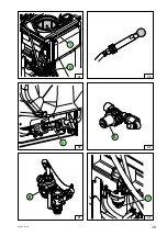
- Connect the hopper's piping (6) to the valve (1) located on the sprayer.
- Dip the filling stick (4) into the tank of your sprayer.
- Hook the top of the filling stick under the edge of manhole.
- Fill the tank partly, (approx. 100 litres, see filling operation, pages 16 and 26).
- Lift the cover of the hopper.
- Fill the hopper with phytosanitary products.
- Adjust valves:

  Manual control version:

  ▪ Put the valve (V1) in position   (figure 25 page 31).
  ▪ Valve (V2) in position 


(figure 29).

  ▪ Valve (1) in position 


(figure 31).

  Electric control version:

  ▪ Put the valve (V1) in position   (figure 25 page 31).
  ▪ Valve (V2) in position 


(figure 30).

  ▪ Valve (1) in position 


(figure 31).

  In both cases:

  ▪ Engage the tractor's power take-off and increase its speed to 540 rpm.
  ▪ To rapidly empty the hopper:
 

▪ Replace the cover,


▪ open the valve (5) in position   (figure 31).

- The product is draw up into and incorporated in the sprayer's tank.

RINSING THE HOPPER

- Open the valve (2) in position   (figure 31) which actuates the rinsing boom (1) (figure 32).

RINSING THE CANS

- Position the product can on part (2) (figure 32).
- Open the valve (3) in position   (figure 31) to actuate the cleaning nozzle (3) (figure 32).

AFTER THESE OPERATIONS

- Adjust:
  ▪ Valve (1) in position 


(figure 31).

- You can now finish the tank's filling.

- After the filling operation (figure 33):
  ▪ Remove filler hose (2),
  ▪ refit the plug (1).

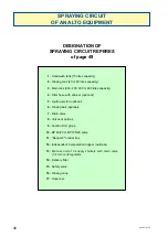
INCORPORATION HOPPER - ALTO 300/400/600/800

Содержание ALTO 300

Страница 1: ...prayers see manual 82 471 Tables of NOZAL nozzles see manual 82 467 BERJUST 2 see manual 82 389 TLP 7 boom see manual 82 232 RA boom see manual 82 354 GC 9 boom see manual 82 235 XR 12 boom see manual...

Страница 2: ...2 82493 ALTO...

Страница 3: ...er D P M version ALTO 600 800 Adjustment of the compensated return 24 Filling 26 Spraying 28 Rinsing the equipment 30 Other sprayer functions Incorporation hopper ALTO 300 400 600 800 34 Height of the...

Страница 4: ...4 82493 ALTO...

Страница 5: ...sures Hitching unhitching Maintenance Adapting the PTO shaft Meaning of the safety stickers Acceptable use of the sprayer Counter indications Warning See Safety checks maintenance of the Sprayers manu...

Страница 6: ...sion ALTO 600 800 Distribution BERTHOUD distribution manual control unit including Glycerine pressure gauge 0 25 bar diameter 63 mm Constant pressure version 1 general quarter turn shutoff valve 1 man...

Страница 7: ...LTO 600 ALTO 800 Overall width 2 610 2 700 Overall length 1 730 2 150 Overall height 2 200 2 540 C B A SOUND MEASUREMENTS Atmospheric noise emitted by Mounted sprayer ALTO with BP 60 or BP 105 pump Co...

Страница 8: ...rayer s identification plate is located on the chassis see pages 9 and 10 The box Type Berthoud is made up of letters and figures Example ALT M 06 XR 12 12 width 12 metres XR XRT 12 and XRS 12 boom TL...

Страница 9: ...417 597 418 630 418 629 417 575 417 579 417 586 417 289 ATTENTION ATTENTION VORSICHT ATENCION ZI Bois Baron 1 rue de l industrie Pulv risateurs Sprayers Spritzger te 69220 BELLEVILLE s SA NE France P...

Страница 10: ...9 417 586 417 289 ATTENTION ATTENTION VORSICHT ATENCION ATT ENT ION ATT ENT ION VOR SIC HT ATE NCI ON ZI Bois Baron 1 rue de l industrie Pulv risateurs Sprayers Spritzger te 69220 BELLEVILLE s SA NE F...

Страница 11: ...g power take off speed Checking tractor advance speed Checking engine speed Checking flow hectare Checking tractor wheel circumference See Safety checks maintenance of the Sprayers manual No 82 471 ST...

Страница 12: ...he condition of the hoist as well as the boom s lifting rope Check the oil levels and the greasing of the various elements see Lubrication and greasing section Check the cleanness of the filters Sucti...

Страница 13: ...1 according to the selected options With the valves of options figure 2 In spraying mode The valve V3 must always be in position opened In option mode The valve V2 is in position Adjust the regulator...

Страница 14: ...14 82493 ALTO...

Страница 15: ...5 82493 ALTO CHOICE OF NOZZLES AND TABLES OF FLOW RATES See NOZAL nozzles Manual No 82 467 Using the sprayer Constant pressure version ALTO 300 400 600 800 Berjust 2 monitor option see manual No 82 38...

Страница 16: ...e 5 Connect it directly to the hydro injector s 1 suction hose Remove the plug 2 and connect the filler hose 3 Adjusting the distribution unit figure 6 Put the valve V1 in position figure 3 Put the su...

Страница 17: ...17 82493 ALTO 5 6 4 3 V4 V1 1 1 2 3 4 2 3 V2...

Страница 18: ...re 260 litres ha Selected nozzles ALUMINE AFX 0 50 m spaced Possible choice ALUMINE AFX BLUE 3 5 bar 256 litres ha TO OBTAIN REQUIRED VOLUME HECTARE Fit the chosen nozzles Put the handle of the main v...

Страница 19: ...19 82493 ALTO 7 8 1 1 2 3 4 V2 V2...

Страница 20: ...nsing tank is empty This operation is not enough when changing the chemical products RINSING THE SPRAYING CIRCUIT WITH THE MAIN TANK For the chemical product changing Sprayer off Put 300 litres of cle...

Страница 21: ...21 82493 ALTO 9 10 1 V1 V2...

Страница 22: ...22 82493 ALTO...

Страница 23: ...23 82493 ALTO CHOICE OF NOZZLES AND TABLES OF FLOW RATES See NOZAL nozzles manual No 82 467 Using the sprayer D P M version ALTO 600 800 Berjust 2 monitor option see manual No 82 389...

Страница 24: ...TYPE AFX RFX ALX KWIX RRX ARX green 80 1 7 2 0 2 2 2 4 2 5 2 8 3 1 3 5 AFX RFX ALX KWIX RRX ARX yellow 80 2 2 2 4 2 6 2 8 3 0 3 3 3 7 4 1 AFX RFX ALX KWIX RRX ARX blue 110 2 8 3 0 3 3 3 5 3 7 4 1 4 6...

Страница 25: ...25 82493 ALTO 11 12 13 1 3 2 V 1 1 3 2 V2 4...

Страница 26: ...ut the handle of the main valve V2 in position figure 16 Put the handle of the valve 1 in position figure 17 Make sure that the valve V3 located under the block is in closed position figure 18 With mo...

Страница 27: ...27 82493 ALTO 16 17 19 18 14 V4 V1 15 1 2 3 1 V2 V3 V2...

Страница 28: ...ntrol valve switch 1 figure 23 and 4 figure 24 From this moment you can start spraying and you will obtain a FIXED VOLUME HECTARE dose within a wide range of power take off speeds and therefore engine...

Страница 29: ...29 82493 ALTO ON OFF 20 21 24 23 D P Elec 2 4 1 1 1 V V 22 V2 V2 1 2 3...

Страница 30: ...enough when changing the chemical products RINSING THE SPRAYING CIRCUIT WITH THE MAIN TANK For the chemical product changing Sprayer off Put 300 litres of clear water with a cleaning product All Clear...

Страница 31: ...31 82493 ALTO 27 D P Elec 1 ON OFF 28 2 4 1 1 V 26 25 V4 V1 1 2 V2 V V2 3...

Страница 32: ...32 82493 ALTO...

Страница 33: ...33 82493 ALTO OTHER SPRAYER FUNCTIONS...

Страница 34: ...tion figure 29 Valve 1 in position figure 31 Electric control version Put the valve V1 in position figure 25 page 31 Valve V2 in position figure 30 Valve 1 in position figure 31 In both cases Engage t...

Страница 35: ...35 82493 ALTO a b a a b b 31 30 32 1 2 3 4 5 6 2 3 29 1 33 1 2 V2 V V2...

Страница 36: ...TANK Hygiene and comfort a 15 litre clean water tank 1 figure 35 allows you to wash your hands or any other part of your body face eyes that may have come in contact with the product Positioned in fr...

Страница 37: ...37 82493 ALTO 35 36 34 V4 Alto 300 400 Alto 300 400 Alto 600 800 Alto 600 800 1 1 3 2 2 2 3 2...

Страница 38: ...onal filtration To remove the filter cartridge mesh 4 10 unscrew the filter body 1 figure 42 using a 27 mm wrench wrench not supplied with the machine The filter cartridge needs to be cleaned after ea...

Страница 39: ...39 82493 ALTO 37 41 40 38 39 1 42 1 S 1 2 E...

Страница 40: ...40 82493 ALTO...

Страница 41: ...41 82493 ALTO MAINTENANCE OF THE SPRAYER See Safety checks maintenance of the Sprayers manual No 82 471...

Страница 42: ...te is 10 to 15 greater than their initial flow rate To do this use the FLOW TEST BERTHOUD reference 765 241 or the FLOW RATE GAUGE BERTHOUD reference 778 887 Tank Check that there is no foreign matter...

Страница 43: ...s and clean them Reassemble See chapter Servicing the boom The sprayer should be wintered in a clean condition see above Rinse the circuit completely with a cleaning product Drain the tank Rinse with...

Страница 44: ...hly operating the machine for several minutes with clear water Drain the piping particularly if there is a risk of frost After cleaning the boom with a high pressure jet grease the ram shafts to preve...

Страница 45: ...rough the level plug 1 If there is not enough oil remove the stirrups 2 the bell assembly 3 and the plug 4 The oil must be flush with the bottom edge of the sump hole Oil capacity for a BP 60 20 pump...

Страница 46: ...46 82493 ALTO...

Страница 47: ...47 82493 ALTO MAINTENANCE DIAGRAM SPRAYING CIRCUIT...

Страница 48: ...sing ball optional 7 Drain valve 8 Valves of options 9 Suction filter group 10 BP 60 20 or BP 105 20 pump 11 Berjust 2 control box 12 Independent incorporation hopper optional 13 Manual unit of 3 supp...

Страница 49: ...49 82493 ALTO 1 2 3 7 4 9 6 5 8 10 17 12 13 14 16 15 ON OFF 11...

Страница 50: ...rogrammed the brand of nozzles and their colours nozzle Nozzle 1 NOTE At the start of each treatment season check the real flow rates of your nozzles Wheel circumference Number of pulses Remember your...

Страница 51: ...51 82493 ALTO Note on the treatments Carried out during the season Date Field Treatment Product Dose Volume l ha Nozzle Pressure Speed km h...

Страница 52: ...E S SA NE FRANCE Tel 33 4 06 50 50 Fax 33 4 74 06 50 77 Internet www berthoud com E mail berthoud agricole berthoud com Because of our policy of constant product improvement we reserve the right to mo...

Отзывы: