


30
82493 - ALTO
RINSING THE SPRAYING CIRCUIT WITH THE RINSING TANK
- Sprayer off.
- Disengage the power take-off.
Manual control version:
▪ Set the manual regulating valve (V) at position
12
, or use the switch (1) (figure 27) to increase the pressure,
thereby closing the electric regulating valve.
▪ Supply shutters (1) in position , (figure 27).
▪ Valve (V2) in position
(figure 27).
▪ Valve (V1) in position
(figure 25).
▪
With options:
Valve (1) in position and valve (2) in position
(figure 26).
Electric control version:
▪ Fully close the regulating valve (V) or use the switch (4) (figure 28) to increase the pressure, thereby closing
the electric regulating valve.
▪ Valve (V1) in position (figure 25).
▪
With options:
Valve (1) in position and valve (2) in position
(figure 26).
▪ Valve (V2) in position (figure 28).
▪ Control switches (2) and (3) lowered (figure 28).
- In both cases, engage the power take-off to idle at
150 rpm max
until the rinsing tank is empty.
- Put the manual or electric regulating valve back at its initial position.
This operation is not enough when changing the chemical products.
RINSING THE SPRAYING CIRCUIT WITH THE MAIN TANK
For the chemical product changing.
- Sprayer off.
- Put 300 litres of clear water with a cleaning product (
ALL CLEAR
type) into the main tank.
Manual control version:
▪ Set the manual regulating valve (V) at position
12
, or use the switch (1) (figure 27) to increase the pressure,
thereby closing the electric regulating valve.
▪ Supply shutters (1) in position , (figure 27).
▪ Valve (V2) in position
(figure 27).
▪ Valve (V1) in position
(figure 25).
▪
With options:
Valve (1) in position and valve (2) in position
(figure 26).
Electric control version:
▪ Fully close the regulating valve (V) or use the switch (4) (figure 28) to increase the pressure, thereby closing
the electric regulating valve.
▪ Valve (V1) in position (figure 25).
▪
With options:
Valve (1) in position and valve (2) in position
(figure 26).
▪ Valve (V2) in position (figure 28).
▪ Control switches (2) and (3) lowered (figure 28).
In both cases:
- Engage the power take-off to idle at
150 rpm max
until the main tank is empty.
- Put the manual or electric regulating valve (V) back at its initial position.
After rinsing the spraying circuit,
drain the main tank with the valve (V4) (figure 25).
RINSING THE EQUIPMENT
Содержание ALTO 300
Страница 2: ...2 82493 ALTO...
Страница 4: ...4 82493 ALTO...
Страница 14: ...14 82493 ALTO...
Страница 17: ...17 82493 ALTO 5 6 4 3 V4 V1 1 1 2 3 4 2 3 V2...
Страница 19: ...19 82493 ALTO 7 8 1 1 2 3 4 V2 V2...
Страница 21: ...21 82493 ALTO 9 10 1 V1 V2...
Страница 22: ...22 82493 ALTO...
Страница 25: ...25 82493 ALTO 11 12 13 1 3 2 V 1 1 3 2 V2 4...
Страница 27: ...27 82493 ALTO 16 17 19 18 14 V4 V1 15 1 2 3 1 V2 V3 V2...
Страница 29: ...29 82493 ALTO ON OFF 20 21 24 23 D P Elec 2 4 1 1 1 V V 22 V2 V2 1 2 3...
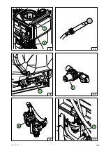
Страница 31: ...31 82493 ALTO 27 D P Elec 1 ON OFF 28 2 4 1 1 V 26 25 V4 V1 1 2 V2 V V2 3...
Страница 32: ...32 82493 ALTO...
Страница 33: ...33 82493 ALTO OTHER SPRAYER FUNCTIONS...
Страница 35: ...35 82493 ALTO a b a a b b 31 30 32 1 2 3 4 5 6 2 3 29 1 33 1 2 V2 V V2...
Страница 37: ...37 82493 ALTO 35 36 34 V4 Alto 300 400 Alto 300 400 Alto 600 800 Alto 600 800 1 1 3 2 2 2 3 2...
Страница 39: ...39 82493 ALTO 37 41 40 38 39 1 42 1 S 1 2 E...
Страница 40: ...40 82493 ALTO...
Страница 41: ...41 82493 ALTO MAINTENANCE OF THE SPRAYER See Safety checks maintenance of the Sprayers manual No 82 471...
Страница 46: ...46 82493 ALTO...
Страница 47: ...47 82493 ALTO MAINTENANCE DIAGRAM SPRAYING CIRCUIT...
Страница 49: ...49 82493 ALTO 1 2 3 7 4 9 6 5 8 10 17 12 13 14 16 15 ON OFF 11...


