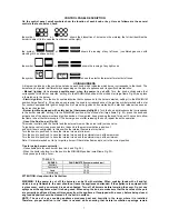
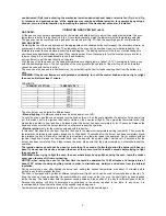
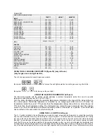
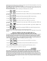
background image


3

IMPORTANT INFORMATION FOR INSTALLING THE APPLIANCE 

The cooker can be installed separately, as a freestanding unit, or between kitchen units or between a kitchen 
unit and the wall. The device must be installed in accordance with the regulations stated in UNI 7129 and UNI 
7131 standards.


This appliance is not connected to devices which exhaust combustion products. 
Special attention must be focused on the prescriptions described below regarding room aeration and 
ventilation. Any hanging cabinets installed above the work surface must be located at a distance of no less than 
700 mm.


ROOM VENTILATION 

To ensure that the appliance operate correctly, the room where it is installed must be continuously ventilated. The room 
volume should not be less than 25 m³ and the quantity of air needed shall be based on the regular combustion of gas and 
on the ventilation of the room. Natural air will flow through permanent openings in the walls of the room to be ventilated: 
these openings will be connected with the outside environment and shall have a minimum cross-section defined by the 
current national standards regarding room ventilation (see Fig. 3). 
These openings shall be built so that they cannot be clogged. 
Indirect ventilation is also permitted by taking air from the rooms adjacent to the one to be ventilated.


LOCATION AND AERATION 

The gas cooking appliances must always evacuate the combustion products by means of hoods connected to chimneys, 
flues or directly outside (see Fig. 4). If a hood cannot be installed, it is possible to use a fan installed on a window or 
directly facing outdoors, to be operated together with the appliance (see Fig. 5), provided that there is strict compliance 
with the ventilation regulations. 


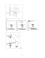
HEIGHT-ADJUSTABLE FEET (figure.6)


The feet are packed in the top box. 

The feet should be installed with the cooker close to its final installation position; the feet are not safe to move the cooker 
long distances.   
After unpacking the cooker, lift it with your foot, to fit the cooker feet in the bases at the bottom.  Slowly lower the cooker 
so its weight is resting on the feet and on the assembly fixings.  We recommend using a lifting device or pallet instead of 
tilting the cooker. 


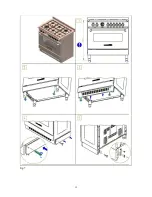
INSTALLING THE TOEKICK PANEL (only available for some models) 

After installing the feet, install the cooker skirt as shown in the pictures in Figure 7 


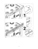
INSTALLING THE RISER


Remove the 2 screws securing the hob at the rear, as shown in (figure 8) 
Put the upstand in place and secure at the bottom with the two screws, as shown in (figure 8) 
Secure the middle of the upstand using the screws provided with the upstand (figure 8) 


INSTALLING THE HOB RAIL AND OVEN HANDLE  

The rail and handle are packed with the upstand. 
The rail is only available on some models. 
Assemble the hob rail and oven handle as shown in the pictures

 (fig.9A –9B –9C) 


INSTALLING THE SYSTEM TO PREVENT OVERTURNING 

To prevent the appliance from accidentally overturning, the system provided must be installed.  Install the system as 
shown in the fig.10.


APPLIANCE GAS CONNECTION 

Before connecting the appliance to the gas network, make sure that the data on the label attached to the food 
warmer drawer or on the back of the cooker are compatible with what is indicated for the gas distribution 
network. 
A label attached to the last page of this handbook and in the food warmer drawer (or on the back) of the 
appliance indicates the appliance adjustment conditions: type of gas and operating pressure. 


IMPORTANT: This appliance must be installed in compliance with current national standards in force and used 
only in a well-ventilated room. 
WARNING: It should be recalled that the appliance utilises a threaded 1/2" gas cylindrical male fitting according 
to UNI-ISO 228-1. 
To connect the appliance to the gas network with a flexible rubber hose, a supplemental hose nipple fitting is 
needed (see Fig. 11) which is supplied with the appliance. 


Содержание 90x60 cm (type M92/M92V)Dual oven

Страница 1: ...to persons caused by incorrect installation or improper use of the appliance The manufacturer is not responsible for any inaccuracies due to printing or transcription errors contained in this booklet In addition the appearance of the figures reported is also purely indicative The manufacturer reserves the right to make changes to its products when considered necessary and useful without affecting ...

Страница 2: ...c Equipment WEEE This guideline is the frame of a European wide validity of return and recycling on Waste Electrical and Electronic Equipment INSTALLER INFORMATION The installation all adjustments transformations and maintenance listed in this part of the manual must be carried out only by skilled personnel Improper installation may cause damage to persons animals or property for which the manufac...

Страница 3: ...o its final installation position the feet are not safe to move the cooker long distances After unpacking the cooker lift it with your foot to fit the cooker feet in the bases at the bottom Slowly lower the cooker so its weight is resting on the feet and on the assembly fixings We recommend using a lifting device or pallet instead of tilting the cooker INSTALLING THE TOEKICK PANEL only available f...

Страница 4: ...0 6 516 36 Semi Rapid Butane G30 30 66 127 1 75 1505 0 6 516 36 Propane G31 37 66 125 1 75 1505 0 6 516 36 Natural G20 20 129 286 3 2580 1 05 903 52 Rapid Butane G30 30 87 218 3 2580 1 05 903 52 Propane G31 37 87 214 3 2580 1 05 903 52 Natural G20 20 In 70 476 5 4300 0 48 413 In 34 reg Out 110 out 65 reg Dual Butane G30 30 In 46 334 4 6 3956 0 48 413 In 34 Out 69 out 65 Propane G31 37 In 46 328 4 ...

Страница 5: ...st be positioned so that an overtemperature of 75 K will not be reached at any point Do not use reductions adapters or splitters since they might cause false contacts and lead to dangerous overheating When the connection is made directly to the electric network Use a device that ensures disconnection from the mains in which the contacts are opened to a distance that permits complete disconnection ...

Страница 6: ...ture in C of the place where the appliance is installed APPLIANCE MAINTENANCE REPLACING PARTS Before performing any maintenance operation disconnect the appliance from the gas supply and electricity network To replace parts such as knobs and burners just remove them from the seats without disassembling any part of the cooker To replace parts such as nozzle supports valves and electric components f...

Страница 7: ...conds to allow the flame to heat the thermocouple If the burner goes out after releasing the knob repeat the entire operation Use of the Dual burner Fig 24 This model controls both the central and the external crown of the burner with just one valve To ignite the central crown press and turn the knob to the maximum delivery position 1 and hold it down until ignition in this position the internal f...

Страница 8: ...the indicator At the same time put a lit match next to the ignition tube that is visible on the oven level fig 28 Then press the thermostat knob this makes the gas start to flow and keep it pressed after the burner has been completely lit for 10 seconds Release the knob and make sure that the burner remains on otherwise repeat the operation Electric ignition only for the models equipped with this ...

Страница 9: ...ing from 50 C to 250 C fig 31 Turn the knob clockwise and align the selected temperature indicated on the ring with the index etched on the control panel Thermostat operation is indicated by an orange light which will turn off when the temperature inside the oven is 10 C greater than the temperature setting and will turn on when the oven is 10 C less than the temperature setting The thermostat can...

Страница 10: ...ostat combined with a switch used to turn on the elements The electric oven can be combined with an electric grill The oven is heated by 2 elements one on the top and one on the bottom Turning the knob fig 33 turns on the bottom element and the top external elements while the thermostat is used to set the temperature ranging from 50 C to 250 C It can be adjusted using the scale indicated on the ri...

Страница 11: ...ir circulation in the horizontal direction Thanks to this type of operation the ventilated oven can be used for different types of cooking at the same time without changing the taste of each food Only some models are equipped with a removable metallic filter applied to the rear screen which collects the fat while a roast is cooking Therefore it is recommended to remove this fat periodically washin...

Страница 12: ...ent and fan motor With cookers with a 9 setting change over switch set the 9 0 switch to the relative position and the electric thermostat to the temperature required to turn on the grill heating element and fan motor IMPORTANT When using the electric grill with fan do not turn the thermostat knob to not more than 175 C between 150 and 200 C to prevent overheating the oven front the oven has been ...

Страница 13: ... CLEANING THE APPLIANCE Before any cleaning unplug the appliance and turn off the gas tap Do not use steam cleaners to clean the appliance Cleaning the hob Clean the burner heads enamelled steel pan supports enamelled caps and flame spreaders regularly using warm soapy water Rinse and dry well Use a cloth to wipe away any liquids spilt from pans If the gas tap does not open or close easily do not ...

Страница 14: ...14 Fig 1 Fig 3 Fig 4 Fig 5 Fig 6 ...

Страница 15: ...15 Fig 7 ...

Страница 16: ...16 Fig 8 ...

Страница 17: ...17 Fig 9A ...

Страница 18: ...18 Fig 9B ...

Страница 19: ...19 Fig 9C ...

Страница 20: ...20 Fig 10 Fig 11 fig 12 fig 13 ...

Страница 21: ...21 fig 14 fig 15 fig 16 Fig 17 Fig 18 Fig 19 T fig 20 fig 21 fig 21A fig 21B Fig 22 Fig 23 Fig 23 Fig 24 ...

Страница 22: ...22 Fig 24 Fig 25 Fig 26 fig 27 fig 27 fig 28 fig 29 Fig 30 Fig 30 Fig 31 Fig 31 Fig 32 Fig 32 Fig 33 ...

Страница 23: ...23 Fig 33 Fig 34 Fig 35 Fig 36 ...

Страница 24: ...24 Cod 310768 ...

Отзывы: