7
CONTROL PANEL DESCRIPTION
On the control panel, small symbols show the function of each knob or key. Here as follows are the several
controls that a cooker can have:
the symbol
or
shows the disposition of burners on the worktop, the full dot identifies the
burner in object (in this case the front burner on the right).
the symbol
or
shows the running of any left oven (ventilated gas oven with
electric grill, 9 positions switch)
the symbol
or
shows the running of any right oven
the symbol
or
shows the electric thermostat for electric left oven
USING BURNERS
A diagram is etched on the control panel above each knob which indicates which burner corresponds to that knob. The
burners can be ignited in different ways depending on the type of appliance and its specific characteristics:
- Manual lighting (it is always possible even when the power is cut off):
Turn the knob anticlockwise that
corresponds to the burner selected, setting it to the MAXIMUM position at the etched star (large flame Fig.23) and place
a lit match up to the burner.
- Electric ignition:
Turn the knob counterclockwise that corresponds to the burner selected, setting it to the MAXIMUM
position (large flame Fig. 23) and keep on pressing the knob in correspondence of the ignition symbol marked with a star
(for cookers equipped with ignition trough knob) or press the ignition button marked with a star and release it as soon as
the burner has ignited.
- Burner ignition equipped with safety device (thermocouple)(fig.25):
Turn the knob anticlockwise that corresponds
to the burner selected, setting it to the MAXIMUM position at the etched star (large flame Fig. 23), press the knob and
activate one of the above-mentioned ignition devices. Once ignited, keep pressing the knob for about 10 seconds to allow
the flame to heat the thermocouple. If the burner goes out after releasing the knob, repeat the entire operation.
- Use of the Dual burner (Fig.24)
This model controls both the central and the external crown of the burner with just one valve.
To ignite the central crown press and turn the knob to the maximum delivery position 1
and hold it down until ignition; in this position the internal flame are at maximum.
Turn the knob to position 2 to have the internal crown at minimum.
Turn the knob to position 3 to have the internal crown and the external crown at the maximum.
Turn the knob to position 4 to have the internal crown and the external crown at the minimum.
Note: It is recommended not to try to ignite a burner if the relative flame cap is not in the correct position.
Tips for using burners correctly:
- Use suitable pots for each burner (see tab. 4 and Fig. 26).
- When the liquid is boiling, turn the knob to the MINIMUM position (small flame Fig. 23).
- Always use pots with a cover.
TABLE N°5
BURNER
PAN DIAMETER recommended (cm)
Auxiliary 12-14
Semi-rapid 14-26
Rapid 18-26
Double ring
22-26
ATTENTION: Use pots with a flat bottom
WARNING: If the power is cut off, the burners can be lit with matches. When cooking foods with oil and fat,
which are very flammable, the user should not leave the appliance unattended. If the appliance is equipped with
a glass cover, such a cover may break when heated. Turn off all burners before lowering the cover. Do not use
sprays near the appliance when it is being used. When using the burners, make sure that the handles of the pots
are correctly positioned. Keep children away from the appliance. If equipped with a cover, before being closed,
any food deposits should be cleaned off the built-in surface.
NOTE: The use of a gas cooking appliance produces heat and humidity in the room where it is installed.
Therefore, proper aeration in the room is needed while ensuring that natural ventilation openings remain
Содержание 90x60 cm (type M92/M92V)Dual oven
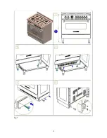
Страница 14: ...14 Fig 1 Fig 3 Fig 4 Fig 5 Fig 6 ...
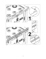
Страница 15: ...15 Fig 7 ...
Страница 16: ...16 Fig 8 ...
Страница 17: ...17 Fig 9A ...
Страница 18: ...18 Fig 9B ...
Страница 19: ...19 Fig 9C ...
Страница 20: ...20 Fig 10 Fig 11 fig 12 fig 13 ...
Страница 21: ...21 fig 14 fig 15 fig 16 Fig 17 Fig 18 Fig 19 T fig 20 fig 21 fig 21A fig 21B Fig 22 Fig 23 Fig 23 Fig 24 ...
Страница 22: ...22 Fig 24 Fig 25 Fig 26 fig 27 fig 27 fig 28 fig 29 Fig 30 Fig 30 Fig 31 Fig 31 Fig 32 Fig 32 Fig 33 ...
Страница 23: ...23 Fig 33 Fig 34 Fig 35 Fig 36 ...
Страница 24: ...24 Cod 310768 ...


