27
TECHNICAL ASSISTANCE CENTRE
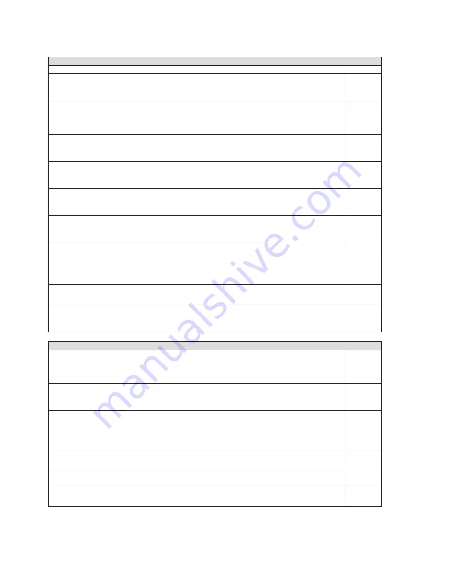
13 CHECKS DURING AND AFTER INITIAL START-UP
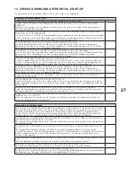
On completion of the installation, perform the checks listed in the table below.
Checking the solar collector circuit
CHECK THAT THE SOLAR COLLECTOR CIRCUIT HAS BEEN PROPERLY BLED
THERE ARE NO CONNECTIONS BETWEEN THE SOLAR HEATING CIRCUIT AND OTHER WATER
SUPPLIES
External water supplies such as automatic filling systems can alter the strength of the water-glycol mix
and lead to serious frost damage.
THE PROPYLENE GLYCOL DELIVERED WITH THE COLLECTORS HAS BEEN USED TO MAKE THE
WATER-GLYCOL ANTI-FREEZE MIX
It is essential to use the non-toxic, biodegradable and environmentally friendly propylene glycol supplied
with the collectors. The use of other types of anti-freeze mix can damage the solar water heating system
because other products form residues and deposits at high temperatures.
THE PERCENTAGE OF GLYCOL IN THE MIX IS BETWEEN 30% AND 50%
The percentage of glycol in the anti-freeze mix must be adjusted to suit the minimum temperature
expected in the place of installation. 50% glycol provides anti-freeze protection down to -32°C. Higher
percentages can cause the mix to become too dense.
THE DENSITY OF THE HEAT TRANSFER LIQUID IS BETWEEN 1.029 AND 1.045 kg/dm
3
Use an instrument like a refractometer or densimeter to check the density of the anti-freeze. Excessively
dense mixes cause solid deposits to form at high temperatures and prevent proper circulation.
Insufficiently dense mixes expose the system to the risk of freezing.
THE pH OF THE HEAT TRANSFER LIQUID IS HIGHER THAN 7
Use litmus paper to ensure that the pH of the mix is not too acid. This check is not necessary when the
system is started up for the first time, but becomes necessary after the system has been operating for
more than 2 years. If the mix becomes acidic, then the heat transfer liquid will be corrosive.
THE SAFETY VALVE OPERATES AT 6 BAR AND CANNOT BE SHUT OFF BY ANY COCKS
The percentage of glycol in the anti-freeze mix must be adjusted to suit the minimum temperature
expected in the place of installation. 50% glycol provides anti-freeze protection down to -32°C. Higher
percentages can cause the mix to become too dense
CHECK THAT ALL THE PIPES IN THE WATER CIRCUIT HAVE BEEN INSULATED IN CONFORMITY TO
RELEVANT STANDARDS
INITIAL PRESSURE IN THE SOLAR COLLECTOR CIRCUIT
Check that the pressure in the circuit, when cold, is 1.5 bar at the collector field. Low pressure leads to
lower evaporation temperatures in the collectors during the stagnation phase. The evaporation point must
be kept high.
THE FLOW RATE THROUGH THE CIRCUIT IS 0.5 l/min FOR EVERY m
2
OF COLLECTOR AREA
Adjust the flow regulator to achieve a flow rate of 0.5 l/min for every m
2
of collector area. For example, if
you have a total of 5 m
2
of collector area, flow rate must be 2.5 - 3 l/min.
CHECK THAT THE TEMPERATURE DIFFERENTIAL BETWEEN THE COLLECTOR OUTLET AND RETURN
IS BETWEEN 10°C AND 25°C
When the solar circuit is functioning, the temperature differential between the collector outlet and the
return should be between 10°C and 25°C.
Temperature controller checks
THE COLLECTOR TEMPERATURE SENSOR IS CORRECTLY POSITIONED AT THE COLLECTOR OUTLET
The collector temperature sensor must be installed at the outlet from the last collector in the series. The
socket for the temperature sensor is located on the left hand side of the collectors supplied with the
system. Make sure that the cold water return leads to the right hand side of the collectors and that the
temperature sensor is installed in the socket in the left of the leftmost collector in the series.
THE STORAGE CYLINDER TEMPERATURE SENSOR IS CORRECTLY POSITIONED IN THE SOCKET AT
THE BOTTOM OF THE STORAGE CYLINDER
The storage cylinder temperature sensor must be installed to measure water temperature at the bottom of
the storage cylinder.
THE ‘PUMP ON’ ΔT BETWEEN THE COLLECTOR AND THE STORAGE CYLINDER IS BETWEEN 6 AND
10 °C
The temperature differential between the collectors and the storage cylinder that switches on the
circulation pump must be in the range between 6 and 10°C. If the differential is set too low, the circulation
pump will keep cycling on and off. If the temperature differential is set too high, the efficiency of the
system will be reduced.
THE ‘PUMP OFF’ ΔT BETWEEN THE COLLECTOR AND THE STORAGE CYLINDER IS BETWEEN 2 AND
4 °C
The Δt off temperature differential serves to stop the circulation pump cycling on and off.
MAXIMUM STORAGE CYLINDER TEMPERATURE IS BETWEEN 60 AND 80° C.E191
Set storage cylinder temperature to the maximum permitted on the basis of water hardness.
MINIMUM COLLECTOR TEMPERATURE IS BETWEEN 15 AND 20 °C
Set the minimum collector temperature to suit minimum outdoor temperature and so that the temperature
controller receives the signal somewhere in the range between 15 and 20°C.

