


25
F4
F1
(F3)
F2
(F5)
Impulso
A1
A2
ON
1
OFF
2
A3
Impulso
(
)
A3
A3
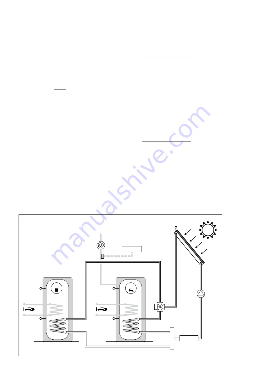
Fig. 2.13
System 5
Outputs:
A1
Collector pump (speed control)
A2
Valve for switching to storage cylinder 2
A3 Additional relay, freely programmable
function
Inputs:
F1
Collector 1 temperature probe
F4
Temperature probe at bottom of stor-
age cylinder 1 / A1 max. temp. moni-
toring (when F3 not fitted)
F2
Temperature probe at bottom of stor-
age cylinder 2 / A1 max. temp. moni-
toring (when F5 not fitted)
F3
(optional) Temperature probe at top
of storage cylinder 1 / A1 max. temp.
monitoring and reference probe dur-
ing heating
F5
(optional) Temperature probe at top
of storage cylinder 2 / A1 max. temp.
monitoring and reference probe dur-
ing heating or for return temperature
control
Impulse (optional) pulse transducer for volu-
metric meter or circulating pump con-
trolled by impulses
Switching conditions for A1
Heat production (difference between storage
cylinder and min. temp.)
ON: F1 - F4 > P30
or F1 - F2 > P32
and F1 > P40
OFF: F1 - F4 < P31 and F1 - F2 < P33
or F1 < P41
Maximum storage cylinder temperature
OFF: F3 (or F4) > P50 and F2 > P51
ON: F3 (or F4) < P50 - 5°C
or F2 < P51 - 5°C
Maximum collector temperature
OFF: F1 > P42
ON: F1 < P42 - 10°C
Switching conditions for A2:
ON: A1 = ON and F3 (or F4) > P50
or F1 – F4 < P31
OFF: A1 = OFF
or F3 (or F4) < P50 - 5°C
or F1 - F4 > P30
impulse
impulse


