ENGLISH
13
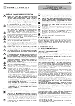
1a GENERAL WARNINGS AND SAFETY
The instruction manual is an integral part of the product and it must there-
fore be kept carefully and must accompany the appliance; if the manual
is lost or damaged, another copy must be requested from the Technical
Assistance Service.
Boiler installation and any other assistance and maintenance opera-
tions must be carried out by qualified personnel according to the
provisions of local legislation.
For installation, it is advisable to contact specialised personnel.
The boiler must only be used for the application foreseen by the
manufacturer. The manufacturer shall not be liable for any damage
to persons, animals or property due to errors in installation, calibra-
tion, maintenance or due to improper use.
The safety and automatic adjustment devices must not be modified,
during the system life cycle, by the manufacturer or supplier.
This appliance produces hot water, therefore it must be connected
to a heating system and/or a domestic hot water mains, compatible
with its performance and output.
In case of water leakage, close the water supply and contact the
Technical Assistance Service immediately.
In case of absence for long periods time, close the gas supply and
switch off the electrical supply main switch. If there is a risk of frost,
drain the boiler.
From time to time check that the operating pressure of the hydraulic
system does not go below 1 bar.
In case of failure and/or malfunctioning, deactivate the appliance,
and do not try to repair or operate directly on it.
Appliance maintenance must be carried out at least once a year:
scheduling it with the Technical Assistance Service will avoid wasting
time and money.
When the product reaches the end of its life it should not be disposed
of as solid urban waste but should be brought to a separated waste
collection facility
Boiler use requires strict observation of some basic safety rules:
Do not use the appliance in any manner other than its intended
purpose.
It is dangerous to touch the appliance with wet or damp body parts
and/or when barefoot.
Under no circumstances cover the intake grids, dissipation grids and
ventilation vents in the installation room with cloths, paper or any
other material.
Do not use electrical switches, telephone or any other object that
causes sparks if there is a smell of gas. Ventilate the room by open
-
ing doors and windows and close the central gas tap.
Do not place anything in the boiler.
Do not perform any cleaning operation if the appliance is not discon-
nected from the mains power supply.
Do not cover or reduce ventilation opening of the room where the
generator is installed.
Do not leave containers and inflammable products in the installation
room.
Do not attempt to repair the appliance in case of failure and/or mal-
functioning.
It is dangerous to pull or twist the electric cables.
Children or unskilled persons must not use the appliance.
Do not carry out operations on sealed elements.
For better use, remember that:
- periodic external cleaning with soapy water not only improves its appear
-
ance but also preserves panelling from corrosion, extending its life cycle;
- if the wall-mounted boiler is enclosed in a hanging unit, leave at least 5
cm for ventilation and maintenance;
- installation of a room thermostat will greatly improve comfort, a more ra-
tional use of the heat and energy saving; the boiler can also be connected
to a programmable timer in order to control the switching on and off of the
appliance during the day or week.
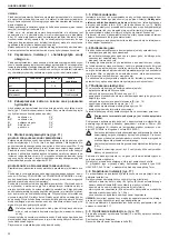
2a SWITCHING ON THE APPLIANCE
Every time the appliance is powered up, a series of data is shown on the
display including the flue gas sensor meter reading (-
C
- XX) (see paragraph
4a - “fault A09”); the automatic purge cycle then starts, lasting around 2
minute
s. During this phase, the three LEDs light up alternately and the sym
-
bol
is shown on the monitor (fig. 25).
To start up the boiler it is necessary to carry out the following operations:
- power the boiler
- open the gas tap to allow the flow of fuel
- set the room thermostat to the required temperature (~20°C)
- turn the mode selector to the desired position:
Winter mode:
by turning the mode selector (fig. 27)
within the marked area,
the boiler provides domestic hot water and heating. If there is a heat re-
quest, the boiler switches on and the boiler status indicator LED lights up
with a fixed green light. The digital monitor indicates the heating water tem
-
perature,
the icon to indicate heating and the flame icon (fig. 29).
If there is a domestic hot water request, the boiler switches on and the
boiler status indicator LED lights up with a fixed green light.
The digital display shows the hot water system temperature, the icon to
indicate the hot water supply and the flame icon (fig. 30).
Adjustment of the heating water temperature
To adjust the heating water temperature, turn the knob with symbol
(fig. 27) within the marked area.
USER GUIDE
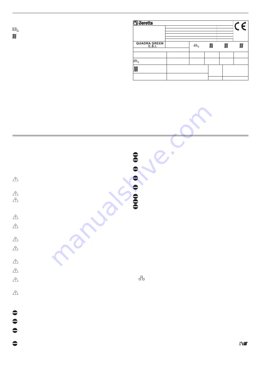
6 SERIAL NUMBER PLATE
Domestic hot water function
Heating function
Qn
Nominal heat delivery
Pn
Nominal heat output
Qm
Reduced heat delivery
Pm
Reduced heat output
IP
Degree of Protection
Pmw
Maximum DHW pressure
Pms
Maximum heating pressure
T
Temperature
D
Specific flow rate
NOx
NOx
class
Serial N.
230 V ~ 50 Hz W
NOx: 5
Pms = bar T=
°
C
Condensing boiler
Caldera de condensación
Centrala in condensatie
Chaudiere a condensation
Brennwertkessel
Kocioł kondensacyjny
IPX5D
Pmw = bar T=
°
C
D: l/min
80-60
°
C
80-60
°
C
50-30
°
C
Qn = kW
Pn = kW
Qn = kW
Pn = kW
Qm = kW
Pm = kW Pn = kW


