Beretta 20084406 Скачать руководство пользователя страница 10

QUADRA GREEN C.S.I.

10

To restore operation (deactivate alarms):

Faults A 01-02-03

Position the function selector to 

 (OFF)

 (fig. 32), wait 5-6 seconds then 

set it to the required position 

 (summer mode) or 

 (winter mode).

If the reset attempts do not reactivate the boiler, contact the Technical As-

sistance Centre.

Fault A 04

In addition to the fault code, the digital display shows the symbol  .

Check the pressure value indicated by the water gauge: if it is less than 0.3 

bar, position the function selector to 

 (OFF) (fig. 32) and adjust the filling 

tap until the pressure reaches a value between 1 and 1.5 bar. Then position 

the mode selector to the desired position

(summer) or 

(winter). 

The boiler will perform one purge cycle lasting approximately 2 minutes. If 

pressure drops are frequent, request the intervention of the Technical As-

sistance Service.

Fault A 06

The boiler operates normally but cannot reliably maintain a constant do-

mestic hot water temperature, which remains set at around 50°C. 

Contact 

the Technical Assistance Centre.

Fault A 07

 - 

A 08

Contact the Technical Assistance Centre.

Fault A 09 with fixed red LED lit

Position the function selector to   (OFF) (fig. 32), wait 5-6 seconds then 

set it to the required position (summer mode) or (winter mode). If the reset 

attempts do not reactivate the boiler, request the intervention of the Techni-

cal Assistance Service.

Fault A 09 with flashing red and green LEDs

The boiler is equipped with an auto-diagnostic system which, based on the 

total number of hours in certain operating conditions, can signal the need 

to clean the primary exchanger (alarm code 09 with flashing red and green 

LEDs and flue gas meter >2.500). Once the cleaning operation has been 

completed, using the special kit supplied as an accessory, the total hour 

meter will need to be reset to zero as follows: 

-  switch off the power supply

-  remove the housing  

-  loosen the fixing screw then turn the instrument panel

-  loosen the fixing screws on the cover (

F

) to access the terminal board 

(fig. 16)  

-  while the boiler is powered up, using a small screwdriver included, press 

the 

CO

 button (fig. 26) for at least 4 seconds, to check the meter has 

been reset, power down then power up the boiler; the meter reading is 

shown on the monitor after the “-C-” sign.


Live electrical parts (230 V AC).

NOTE:

 the meter resetting procedure should be carried out after each 

in-depth cleaning of the primary exchanger or if this latter is replaced. To 

check the status of the total hour meter, multiply the reading by 100 (e.g. 

reading of 18 = 1800 total hours; reading of 1 = 100 total hours).

The boiler continues to operate normally even when the alarm is activated.

Fault A 77

This is an automatic-reset fault, if the boiler does not restart, contact the 

Technical Assistance Centre.

Fixed yellow LED 

Pre-heating function activated. 

Flashing yellow LED

Combustion analysis in progress. 

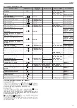
Water pressure switch intervention

flashing 0.5 on/

0.5 off

Temporary stop

Calibration service

ADJ 

flashing 0.5 on/

0.5 off

flashing  0.5  on/0.5 

off

flashing 0.5 on/

0.5 off

Signal

Calibration installer

Chimney sweep

ACO 

flashing  0.5  on/0.5 

off

Signal

Vent cycle

flashing 0.5 on/

1.0 off

flashing  0.5  on/1.0 

off

flashing 0.5 on/

1.0 off

Signal

Pre-heating active function

on

Signal

Pre-heating heat request

 flashing

Signal

External probe presence

Signal

Domestic water heat request

60

°C 

Signal

Heating heat request

80

°C 

Signal

Antifreeze heat request

Signal

Flame present

on

Signal

4.4 Alarm records

The “ALARM RECORDS” function starts automatically once the display has 

been on for 2 hours, or immediately by setting the P1 parameter to 1. 

The records include all the latest alarms, up to a maximum of 5 alarms, and 

they are displayed in sequence by pushing and releasing the P1 button on 

the display board.  If the records are empty (P0=0) or if tracking the same is 

disabled (P1=0), the display function is not available. Alarms are displayed 

in reverse order compared to the order in which they occurred:  this means 

that  the  last  alarm  generated  is  the  first  to  be  displayed.    To  delete  the 

alarms records, simply set parameter P0 to 0. 

NOTE: To get to the P1 button the cover on the control panel must be remo

-

ved and the display board must be identified (fig. 37a). 

PROGRAMMING PARAMETERS 

Functioning of the display can be personalised by programming three pa-

rameters: 

Param.

Default

Description

P0

0

Deletion of alarms records 

(0 = records empty / 1 = records not empty) 

P1

0

Immediate activation of alarm record management 

(0 = delayed records management activated / 1 = 

immediate records management activated

P2

0

Do not change 

When button P1 on the display (fig. 37a) is held down for at least 10 sec, 

the programming procedure is activated.  The three parameters, with their 

respective values, are shown in rotation on the display (fig. 37b).  To edit a 

parameter value, simply push the P1 button again when the required para

-

meter is displayed, and then hold it down until the value switches from 0 to 

1 or vice-versa (approx. 2 sec). 

The programming procedure is closed automatically after 5 minutes, or if 

there is an electrical power failure.

4.5 Boiler configuration 

There is a series of jumpers (JPX) available on the electronic board which 

enable the boiler to be configured.

To access the board, proceed as follows:

-  turn off the main switch on the system

-  loosen the fixing screws on the housing, move the base of the housing 

forwards and then upwards to unhook it from the chassis

-  undo the fixing screws (

E

) from the instrument panel (fig. 14) 

-  loosen the screws (

- fig. 16) to remove the cover of the terminal board 

(230V).

JUMPER JP7 (fig. 38): 

preselection of the most suitable heating temperature adjustment field ac

-

cording to the installation type. 

Jumper not inserted - standard installation

Standa

rd installation 40-80°C

Jumper inserted - floor installation

Floor installation 20-45°C.
In the manufacturing phase, the boiler is configured for standard installa

-

tions.

JP1 

Calibration (Range Rated)

JP2 

Reset heating timer

JP3 

Calibration (see paragraph on “Adjustments”)

JP4 

Absolute domestic hot water thermostat selector

Содержание 20084406

Страница 1: ...EEN 25 C S I 30 C S I Installation and User Manual EN INSTALLER AND USER MANUAL PL INSTRUKCJA OBS UGI INSTALACJI I KONSERWACJI KOT A GAZOWEGO ES MANUAL DE INSTALACI N Y USO RO MANUAL DE INSTALARE SI U...

Страница 2: ...814 2013 ES RO Centrala Quadra Green C S I este fabricat n conformitate cu cerin ele urm toarelor Directive Directiva gaz 2009 142 EEC Directiva eficien Articolul 7 2 i Anexa III din Directiva 92 42...

Страница 3: ...cy pompy 72 PL In some parts of the manual some symbols are used WARNING for actions requiring special care and adequate preparation FORBIDDEN for actions that MUST NOT be performed W niekt rych cz ci...

Страница 4: ...oduction of domestic hot water according to the flue gas discharge device the boiler is classified in categories B23P B53P C13 C23 25 C S I C33 C43 C53 C63 C83 C93 C13x C33x C43x C53x C63x C83x C93x I...

Страница 5: ...tall a filter of suitable dimensions on the gas line if the distribution network contains solid particles Once the appliance has been installed check the connections are sealed according to current in...

Страница 6: ...gas discharge pipe 80 mm through an adaptor 60 80 mm In this case the combustion air is picked up from the boiler instal lation room which must be a suitable technical room with proper ventilation Uni...

Страница 7: ...000 6 200 9 5 100 6 300 12 30 C S I 5 300 6 200 not applicable 5 400 6 300 2 Maximum number of fan rotations r p m Ducting pipes 60 maximum length m CH DHW 25 C S I 4 900 6 100 25 5 000 6 200 30 5 10...

Страница 8: ...de by turning the mode selector fig 27 within the marked area the boiler provides domestic hot water and heating If there is a heat re quest the boiler switches on and the boiler status indicator LED...

Страница 9: ...the operating time allowing greater ease of operation and energy saving On the control panel the green LED flashes ON for 0 5 seconds OFF for 3 5 seconds Reset function To restore operation set the fu...

Страница 10: ...top Calibration service ADJ flashing 0 5 on 0 5 off flashing 0 5 on 0 5 off flashing 0 5 on 0 5 off Signal Calibration installer Chimney sweep ACO flashing 0 5 on 0 5 off Signal Vent cycle flashing 0...

Страница 11: ...ng and of slow switch on must be made strictly in the sequence indicated and only by qualified personnel only disconnect the boiler from the power supply turn the heating water temperature selector to...

Страница 12: ...hen the water temperature reaches the maximum limit about 90 C remains enabled 5 MAINTENANCE The appliance must be systematically controlled at regular intervals to make sure it works correctly and ef...

Страница 13: ...nerator is installed Do not leave containers and inflammable products in the installation room Do not attempt to repair the appliance in case of failure and or mal functioning It is dangerous to pull...

Страница 14: ...s see the chapter on Light signals and faults The digital monitor indicates the fault code detected fig 34 Automatic Temperature Control System function S A R A fig 35 Setting the heating water temper...

Страница 15: ...t it to the required position summer mode or winter mode If the reset attempts do not reactivate the boiler request the intervention of the Technical Assistance Service Fault A 09 with flashing red an...

Страница 16: ...8 4 Average Range Rated efficiency Pn 80 60 97 8 98 0 Average Range Rated efficiency Pn 50 30 106 0 106 1 Electric power CH W 69 78 Electric power DHW W 83 90 Circulator electric power 1 000 l h W 40...

Страница 17: ...rate G31 Air capacity Nm3 h 24 192 30 240 30 240 35 078 Flue gas capacity Nm3 h 24 267 31 209 31 209 36 203 Mass flow of flue gas max min gr s 8 410 2 103 10 513 2 103 10 513 2 523 12 195 2 523 Fan pe...

Страница 18: ...0 24 kW Seasonal space heating energy efficiency s 93 93 Useful heat output At rated heat output and high temperature regime P4 19 5 24 5 kW At 30 of rated heat output and low temperature regime P1 6...

Страница 19: ...i lub wilgotnymi cz ciami cia a i lub b d c boso PL INSTRUKCJA INSTALACJI przed przyst pieniem do wykonania czynno ci zwi zanych z czysz czeniem nale y od czy urz dzenie od sieci elektrycznej ustawiaj...

Страница 20: ...w d sondy 3 5 Zbi r kondensatu Instalacja musi by tak przeprowadzona aby unikn zamarzni cia kon densatu produkowanego przez kocio np poprzez izolacj Nale y zain stalowa odbi r kondensatu na bazie poli...

Страница 21: ...w ale poddawane tym samym warunkom wiatrowym C53 C53x Oddzielne przewody odprowadzenia spalin i poboru powietrza przez cian lub przez dach w miejscach o r nych ci nieniach Przewody odprowadzenia spal...

Страница 22: ...0 38 30 C S I 5 300 6 200 5 5 400 6 300 13 Obroty wentylatora obr min Przewody poprowadzone we wn trznie 80 D ugo maksymalna m C O C W U 25 C S I 4 900 6 100 75 5 000 6 200 90 5 100 6 300 113 30 C S I...

Страница 23: ...ie cych 80 m Kolanko 45 50 12 3 Kolanko 90 50 19 6 Przed u enie 0 5 m 50 6 1 Przed u enie 1 0 m 50 13 5 Przed u enie 2 0 m 50 29 5 ELEMENT 60 Ekwiwalent liniowy w metrach bie cych 80 m Kolanko 45 60 5...

Страница 24: ...j c si e woda jest wolna od jakichkolwiek zanieczyszcze sprawdzi czy podni s si p ywak cylindra wykonanego z two rzywa sztucznego umie ci z powrotem syfon uwa aj c aby nie wyla wody i za mocowa go za...

Страница 25: ...wy czenie Interwencja presostatu wody Miga w czona 0 5 s wy czona 0 5 s Czasowe wy czenie Modyfikacja parametr w ADJ Miga w czona 0 5 s wy czona 0 5 s Miga w czona 0 5 s wy czona 0 5 s Miga w czona 0...

Страница 26: ...a si automatycznie po 5 minutach lub w razie zaniku napi cia 4 5 Konfiguracja kot a Istnieje szereg zworek JPX dost pnych na p ycie elektronicznej kot a kt re umo liwiaj jego konfiguracj Aby uzyska do...

Страница 27: ...ciskaj c przycisk CO na p ycie niezale nie od tego czy wyst puje danie grzania Funkcja nie zostanie aktywowana w przypadku gdy do kot a pod czone jest zdalne sterowanie Kiedy funkcja ta zostanie aktyw...

Страница 28: ...wanie i sprawno kot a konieczne jest pod dawanie go regularnym przegl dom Cz stotliwo przegl d w zale y od szczeg lnych warunk w instalacji oraz u ytkowania jednak przyjmuje si za wskazane coroczne ko...

Страница 29: ...d w elektrycznych Dzieci i osoby bez przygotowania nie powinny u ytkowa urz dzenia Nie nale y rusza uszczelnionych element w W celu optymalnego u ytkowania nale y pami ta e okresowe mycie zewn trzne w...

Страница 30: ...elona dioda UWAGA W przypadku gdy nie mo na odblokowa kot a nale y skontak towa si z Autoryzowanym Serwisem Beretta 3a WY CZANIE Wy czenie tymczasowe W przypadku kr tkiej nieobecno ci nale y ustawi po...

Страница 31: ...zy wymiennik ciep a c o A09 Miga w czona 0 5 s wy czona 0 5 s Miga w czona 0 5 s wy czona 0 5 s Informacja o b dzie B d sondy NTC spalin Czasowe wy czenie Przegrzew na sondzie NTC spalin on Ca kowita...

Страница 32: ...n 80 60 97 8 98 0 rednia sprawno Pn 50 30 106 0 106 1 Moc elektryczna ogrzewanie W 69 78 Moc elektryczna c w u W 83 90 Pompa moc elektryczna 1 000 l h W 40 40 Kategoria II2ELwLs3P II2E3P Kraj przeznac...

Страница 33: ...maks min gr s 9 079 2 165 9 079 2 165 Nat enie przep ywu G27 Przep yw powietrza Nm3 h 23 863 23 863 Przep yw spalin Nm3 h 26 310 26 310 Masowe nat enie przep ywu spalin maks min gr s 9 083 2 166 9 08...

Страница 34: ...rzone ciep o u ytkowe Przy znamionowej mocy cieplnej i w re imie wysokotemperaturowym P4 19 5 24 5 kW Przy znamionowej mocy cieplnej na poziomie 30 i w re imie niskotemperaturowym P1 6 5 8 1 kW Sprawn...

Страница 35: ...esconectada de la red de alimentaci n el ctrica Evitar tapar o reducir dimensionalmente las aperturas de aireaci n del local de instalaci n No dejar contenedores y sustancias inflamables en el local d...

Страница 36: ...ect ndolo al colector u otro dispositivo de uni n que pueda inspeccionarse evitando crear pliegues donde la condensaci n pueda estancarse y eventualmente congelarse El fabricante no se respon sabiliza...

Страница 37: ...aspiraci n realizados con tubos co mercializados y certificados de manera separada 1856 1 C83 C83x Conducto de evacuaci n en chimenea individual o com n y aspiraci n en la pared C93 C93x Evacuaci n en...

Страница 38: ...60 y 67 m para el tubo 80 no aplicable para el tubo 50 Si fuese necesario alcanzar una longitud mayor compensar las p rdidas de carga aumentando el n mero de revoluciones del ventilador como se indic...

Страница 39: ...0 mm o 80 mm o 80 50 mm Longitud Chimenea para entubado 60 50 curvas de 90 80 mm reducci n 80 60 mm 80 50 mm curva de 90 60 mm 50 mm 80 mm Para el encendido de la caldera se deben realizar las siguien...

Страница 40: ...retorno alimentaci n Bloqueo definitivo Limpieza intercambiador primario A09 intermitente 0 5 en cendido 0 5 apagado intermitente 0 5 en cendido 0 5 apagado Se al Aver a NTC humos Parada temporal Sobr...

Страница 41: ...termitente 0 5 en cendido 0 5 apagado intermitente 0 5 encendido 0 5 apagado intermitente 0 5 en cendido 0 5 apagado Se al Calibraci n instalador Deshollinador ACO intermitente 0 5 encendido 0 5 apaga...

Страница 42: ...emperatura de env o sin embargo el usuario puede interactuar con la caldera Si se interviene en la interfaz para modificar la CALEFACCI N no estar disponible el valor de SET POINT CALEFACCI N sino un...

Страница 43: ...o en el cap tulo Regulaciones teniendo como referencia los datos del GPL La transformaci n tiene que ser realizada s lo por personal cualificado Al finalizar la transformaci n aplicare la nueva etique...

Страница 44: ...era de la caja del aire Desenroscar la tuerca que fija la rampa de gas en la v lvula quitar el clip que fija la rampa de gas en el mixer y girar la rampa de gas hacia afuera Quitar el silenciador del...

Страница 45: ...damente los tres led y en la pantalla se muestra el s mbolo fig 25 Para el encendido de la caldera se deben realizar las siguientes operacio nes conectar la alimentaci n el ctrica de la caldera abrir...

Страница 46: ...y sanitaria En este caso la funci n antihielo quedar desactivada Vaciar las instala ciones si hubiese riesgo de heladas 4a SE ALIZACIONES LUMINOSAS Y ANOMAL AS El estado de funcionamiento de la calde...

Страница 47: ...n Bloqueo definitivo Limpieza intercambiador primario A09 intermitente 0 5 en cendido 0 5 apagado intermitente 0 5 en cendido 0 5 apagado Se al Aver a NTC humos Parada temporal Sobretemperatura sonda...

Страница 48: ...d 80 60 97 8 98 0 Rendimiento Pn promedio Range rated 50 30 106 0 106 1 Potencia el ctrica calefacci n W 69 78 Potencia el ctrica agua sanitaria W 83 90 Potencia el ctrica bomba 1 000 h W 40 40 Catego...

Страница 49: ...etro mm 80 80 Longitud m xima m 45 45 40 40 P rdida por la introducci n de una curva de 45 90 m 1 1 5 1 1 5 Instalaci n B23P B53P Di metro mm 80 80 Longitud m xima conducto de evacuaci n m 70 65 Clase...

Страница 50: ...ca nominal Pnominal 20 24 kW Eficiencia energ tica estacional de calefacci n s 93 93 Potencia calor fica til A potencia calor fica nominal y r gimen de alta temperatura P4 19 5 24 5 kW A 30 de potenci...

Страница 51: ...a nu l sa i ambalajul centralei la ndem na copiiilor este interzis s obstruc iona i evacuarea condensului 2 DESCRIEREA CENTRALEI Quadra Green C S I este o central mural n condensa ie de tip C pen tru...

Страница 52: ...oiturilor unde se poate aduna i eventual poate nghe a condensul Produc torul nu este responsabil pentru daune provocate de nerealizarea sistemului de colectare a condensului sau de nghe area acestuia...

Страница 53: ...sau comun i absorb ie prin perete C93 C93x Evacuare prin acoperi asem n tor C33 i absorb ie aer prin tr un co unic existent INSTALA IE FOR AT DESCHIS tip B23P B53P Tub evacuare fum 80 mm fig 20 Tubul...

Страница 54: ...r 25 C S I 4 900 6 100 7 5 000 6 200 9 5 100 6 300 12 30 C S I 5 300 6 200 nu se aplic 5 400 6 300 2 Num r maxim de rota ii ventilator r p m Conducte 60 lungime maxim m nc lzire Ap menajer 25 C S I 4...

Страница 55: ...lui regla i termostatul de ambient la temperatura dorit 20 C roti i selectorul de func ie n pozi ia dorit Iarn rotind selectorul de func ie fig 27 n interiorul cadranului marcat centrala furnizeaz ap...

Страница 56: ...a temperaturii apei calde menajere Pentru a regla temperatura apei calde menajere b i du buc t rie etc roti i butonul marcat cu simbolul fig 33 n sensul orar m ri i tempera tura n sensul contrar o mic...

Страница 57: ...ebuie efectuat dup fiecare cur are a schimb torului principal sau n cazul nlocuirii acestuia Pentru a verifica starea orelor totalizate multiplica i x100 valoarea citit ex valoare citit 18 ore totaliz...

Страница 58: ...axime i minime a maximului de nc lzire i a pornirii lente trebuie efectuate obligatoriu n ordinea indicat i exclusiv de c tre personalul autorizat opri i alimentarea electric aduce i selectorul de tem...

Страница 59: ...tabel dac va loarea este diferit trece i la modificare urm nd procedura descris n capitolul Reglarea vanei de gaz Efectua i controlul arderii Ulterior scoate i sondele analizorului i nchide i prizele...

Страница 60: ...nd u ile i ferestrele i nchide i robinetul general de gaz Nu a eza i obiecte pe central nainte de a executa orice opera iune de cur are deconecta i centrala de la re eaua electric Nu astupa i sau red...

Страница 61: ...e semnalizare n concordan cu simbolul fig 34 nseamn c centrala se afl ntr o stare de oprire temporar vezi capitolul semnaliz ri luminoase i anomalii Pe display ul digital este afi at codul respectivei...

Страница 62: ...re intermitent 0 5 aprins 0 5 stins luminare intermitent 0 5 aprins 0 5 stins Semnalizare Defectare senzor NTC gaze arse Oprire temporar Supratemperatur sond gaze arse aprins Blocare definitiv Flac r...

Страница 63: ...til 30 30 retur 108 9 108 4 Randament Pn medie Gam de puteri 80 60 97 8 98 0 Randament Pn medie Gam de puteri 50 30 106 0 106 1 Putere electric nc lzire W 69 78 Putere electric ACM W 83 90 Putere elec...

Страница 64: ...asic fum max min gr s 9 025 2 140 11 282 2 140 11 282 2 568 13 087 2 568 Debite G31 Debit aer Nm3 h 24 192 30 240 30 240 35 078 Debit fum Nm3 h 24 267 31 209 31 209 36 203 Debit masic fum max min gr s...

Страница 65: ...ferent nc lzirii incintelor s 93 93 Puterea termic util La puterea termic nominal i regim de temperatur ridicat P4 19 5 24 5 kW La 30 din puterea termic nominal i regim de temperatur sc zut P1 6 5 8 1...

Страница 66: ...Antihielo indica que est activo el ciclo antihielo P Precalentamiento agua caliente m s r pido indica que est acti vo un ciclo de precalentamiento el quemador est encendido Temperatura calefacci n ag...

Страница 67: ...wer air vent valve 24 Circulator 25 Flow switch 26 Three way valve motor 27 DHW exchanger ES Elementos funcionales de la cal dera 1 Grifo de llenado 2 Grifo de evacuaci n 3 V lvula gas 4 Sif n 5 V lvu...

Страница 68: ...a NTC c w u 17 Zaw r zwrotny 18 Zaw r nape niania 19 Czujnik przep ywu 20 Kryza ES Circuito hidr ulico AF Entrada agua sanitaria AC Salida agua sanitaria M Alimentaci n calefacci n R Retorno calefacci...

Страница 69: ...QUADRA GREEN C S I 69 fig 4 L N POLARITY IS RECOMMENDED ZALECANA POLARYZACJA L N SE ACONSEJA LA POLARIZACI N L N SE RECOMAND POLARIZAREA L N...

Страница 70: ...S S Sonda NTC temperatura circuito de agua sanitaria P A Presostato de agua T L A Termostato l mite de agua S F Sonda de humos S M Sonda env o temperatura circuito primario S R Sonda retorno temperatu...

Страница 71: ...ka na CN5 fig 5 T A 1 2 3 ES Conexiones exteriores 1 Los equipos de baja tensi n se deber n conectar en el conector CN6 como se indica en la figura C R mando remoto S E Sonda exterior 2 Para efectuar...

Страница 72: ...ciente de agua Por ello la caldera est dotada de un by pass autom tico que regula el caudal correcto de agua en el intercambiador de calefacci n en todas las condiciones de la instalaci n RO SARCINA R...

Страница 73: ...g 8 measured in mm m suri in mm medidas en mm wymiary w mm fig 9 boiler support plate F Listwa monta owa F placa de soporte caldera F cadru de sus inere central F M AC G AF R water gas woda gaz agua g...

Страница 74: ...W POSIBLES CONFIGURACIONES DEL CONDUCTO DE EVACUACI N CONFIGURA II POSIBILE DE EVACUARE A rear outlet B max 50 A wyrzut tylni B maks 50 A salida trasera B m x 50 A ie ire posterioar B max 50 fig 17 fi...

Страница 75: ...emperature Control System S A R A Funkcja SARA Funci n S A R A Func ie S A R A fig 35 fig 36 fig 38 min max fig 37a fig 37b P1 Jumper not inserted standard installation JP7 Mostek wyj ty instalacja gr...

Страница 76: ...acji na maksimum Tornillo de regulaci n potencia m xima Szab lyoz csavar maxim lis teljes tm ny Minimum output adjustment screw ruba regulacji na minimum Tornillo de regulaci n potencia m nima urub de...

Страница 77: ...0 20 15 10 5 0 5 10 15 20 Te mperatura Esterna Te mperatura di 16 C 20 C F G E D B 20 C 25 C 15 C 10 20 30 40 50 60 70 80 90 20 15 10 5 0 5 10 15 20 25 30 D A E CURVE DI TERMOREGOLAZIONE Temperatura e...

Страница 78: ......

Страница 79: ......

Страница 80: ...9 0341 277263 info berettaboilers com www berettaboilers com In order to improve its products Beretta reserves the right to modify the characteristics and information contained in this manual at any t...

Отзывы: