background image


I/O Module Description 


21 

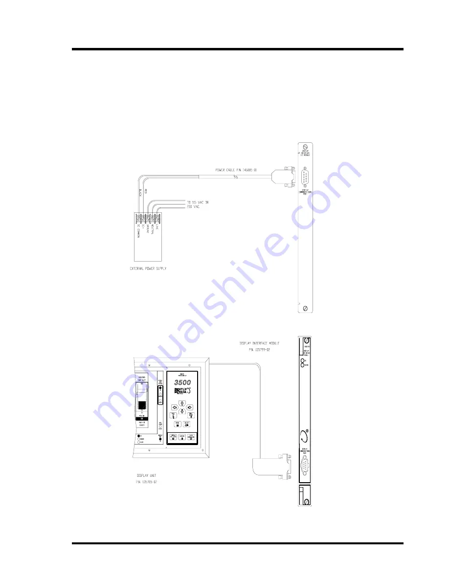
Installing the back-lighted Display Unit in the System Mounting configuration 
(A05) requires an External Power Supply, a back-light Display Interface Module 
(p.n. 135799-02) and a Power Cable (p.n. 146085-01). The following figures 
show typical wiring for the external power supply.  


Содержание 3500/93

Страница 1: ...Part number 137412 01 Revision E April 2002 3500 93 SYSTEM DISPLAY OPERATION AND MAINTENANCE MANUAL...

Страница 2: ...ny human or computer language in any form or by any means electronic mechanical magnetic optical chemical manual or otherwise without the prior written permission of the copyright owner Bently Nevada...

Страница 3: ...rs of the module guidelines for using the 3500 test utilities to verify that the input and output terminals on the module are operating properly 3500 Monitoring System Computer Hardware and Software M...

Страница 4: ...pply 11 3 6 2 Wiring a User Supplied External Power Supply 12 4 Configuration Information 13 4 1 Creating Custom Display Sets 13 4 2 Defining Display Unit Settings 15 4 3 Software Switch 16 4 4 Module...

Страница 5: ...ation Procedure 29 7 3 2 Display Unit Firmware LCD Module Installation Procedure 31 8 Troubleshooting 38 8 1 Self test 38 8 2 LED Conditions 39 8 3 System Event List Messages 41 8 4 Alarm Event List M...

Страница 6: ...3500 93 SYSTEM DISPLAY vi...

Страница 7: ...rap such as 3M Velostat No 2060 before handling or maintaining a printed circuit board Transport and store circuit boards in electrically conductive bags or foil Use extra caution during dry weather R...

Страница 8: ...a reflective LCD module with out a backlight The second version of the Display Unit includes a transflective LCD module with a backlight The Display Unit can be mounted over the front panel of a 3500...

Страница 9: ...how to connect the Display Unit to a Display Interface I O module 1 LEDs Indicate the operating status of the module See section 2 4 2 2 Display Communication Port Retrieves machinery data from this r...

Страница 10: ...Danger Overall Rack Status LED Indicates that at least one of the active channels in the rack is in Danger alarm status 3 Alert Overall Rack Status LED Indicates that at least one of the active chann...

Страница 11: ...Information 5 2 4 2 Display Interface Module LEDs 1 OK LED Indicates that the Display Interface Module is operating correctly 2 TX RX LED Flashes at the rate that messages are received from other 3500...

Страница 12: ...from left to right The power supplies go into slot 0 and the Rack Interface module goes into slot 1 Slots 2 through 15 are called monitoring positions The 3500 93 module can be installed into any of...

Страница 13: ...of the system mount assembly as shown 2 places 3 Remove captive screws 4 places 4 Plug in D Sub cable to the Display Interface Module The Display Interface Module must be installed in slot 15 5 Mount...

Страница 14: ...10 32x 37 Phillips pan head screws 4 places 2 Install the Rack Mount Adapter to the rail using proper screws and washers user supplied 3 Connect the cables Mounting Hardware Description Bently Nevada...

Страница 15: ...cutout 3 Place the panel mount clamp as shown and clamp down on the Display Unit using the 10 32x1 25 Phillips pan head screws 4 places The panel mount clamp dimensions are WxH 409 7 1 25 mm 16 13 0 0...

Страница 16: ...at washers and the 10 32x0 75 screws to clamp down the Display Unit to make a seal between the Display Unit and the Independent Mount Housing 4 places Mounting Hardware Description Bently Nevada Part...

Страница 17: ...Nevada External Power Supply 1 Install the conduit fittings to the independent mount housing 2 places Route the Power and Signal cables in separate conduits 2 Install the brackets to the Display Unit...

Страница 18: ...Wiring a User Supplied External Power Supply Install the Display Unit on the Independent Mount Housing with user supplied power using the installation drawing in section 3 6 1 For item 3 install a ter...

Страница 19: ...ents information and setting software switches You can also check the status of the Display Interface Module and the Display Unit using the verification screen 4 1 Creating Custom Display Sets The 350...

Страница 20: ...n a module 4 The proportional values for all channels in the monitor will appear here 5 Highlight a cell of the display set 6 Highlight a value to be added to the display set 7 Select the Add button T...

Страница 21: ...t settings let you choose the display mode that appears when the unit is turned on the scan rate and the amount of time before the unit returns from the channel information screen to the previous disp...

Страница 22: ...e software If the connection to the rack is lost during the configuration process use this switch to remove the module from Configuration Mode No channel software switches are available for the Displa...

Страница 23: ...Display Interface Module OK status goes Not OK the system OK Relay on the Rack Interface I O Module will be driven Not OK Configuration Fault Indicates if the Display Interface Module configuration i...

Страница 24: ...is the same as the port on the Display Interface Module This I O module lets you connect the communication cable from the Display Unit to the rear of the 3500 rack 5 1 Display Interface I O Module Th...

Страница 25: ...The back lighted Display Unit always requires an external power supply regardless of distance from the 3500 rack Display Interface Extension Cable Part Numbers Bently Nevada Cable Part Numbers Assemb...

Страница 26: ...he I O Module Installing the Display Unit farther than 100 feet from the Display Interface I O Module or installing a back lighted Display Unit requires an external power supply adapter and RS422 exte...

Страница 27: ...hted Display Unit in the System Mounting configuration A05 requires an External Power Supply a back light Display Interface Module p n 135799 02 and a Power Cable p n 146085 01 The following figures s...

Страница 28: ...0 Ft Extension Cable Part Numbers 500 FT Extension Cable A B Part number 130121 A Assembly Instructions 01 Not Assembled 02 Assembled B Insulation Type 01 PVC insulation 02 Teflon insulation 5 3 2 Cab...

Страница 29: ...face I O Module Refer to the 3500 Rack Installation and Maintenance Manual part number 129766 01 install the Display Unit see section 3 connect the Display Unit to the interface module see section 5 2...

Страница 30: ...nel User Defined Sets Highlight a channel Display the next user configured set Display the Channel Information screen for the highlighted channel Channel Information Screen Display the Channel Informa...

Страница 31: ...the unit into self test Upon reset the Display Unit uploads the rack configuration from the Display Interface Module adjust the setting for the contrast of the LCD After pressing the contrast key pres...

Страница 32: ...ually using the arrow keys and page keys or automatically using the scan mode 6 3 1 Display Formats Display Format Description Example Bargraph Displays up to 8 proportional values using graphical rep...

Страница 33: ...omatically Manual scrolling moves through the scroll sequence one channel at a time by pressing the arrow keys or one screen at a time by pressing the page keys When you reach the end of the sequence...

Страница 34: ...Display Unit to the value displayed on the verification screen of a monitor 7 2 Maintaining the Display Unit No routine maintenance or adjustment is required for the Display Unit Use standard househol...

Страница 35: ...monitor Remove the original firmware IC from the monitor PWA Install the upgrade firmware IC into the socket on the monitor PWA Replace the monitor Top Shield Replace the monitor into the 3500 system...

Страница 36: ...ll flathead screwdriver under the lip of either end of the firmware IC The diagram shows the approximate location of the chip to be removed but not necessarily its orientation Step 2 Slightly lift the...

Страница 37: ...diagram under Top Shield Removal Align the holes in the top shield with the standoffs and press down around each standoff until they snap in place 7 3 2 Display Unit Firmware LCD Module Installation...

Страница 38: ...e DU PWA Replace the DU case Replace the DU back into its mounting Run Test Mode and verify correct keypad operation Detailed instructions for some of the steps listed above are provided on the follow...

Страница 39: ...ead screws from the DU backplate and withdraw the DU from the mounting 7 3 2 2 Remove the case from the DU PWA Step 1 Place the DU front side up on a flat static safe surface and remove the eight 6 32...

Страница 40: ...r and thumb push the pigtail connector to the left completely out of the mating receptacle J2 The display cover can now be completely separated from the back plate 7 3 2 3 Remove the original EPROMs f...

Страница 41: ...matched to the notched end of the socket Ensure that the IC is firmly seated in the socket Step 2 Install the U14 upgrade For Display Unit versions 001 xxx Place part number 137354 01 into the U14 so...

Страница 42: ...pgrade LCD module To install the new LCD module you will need to reverse the procedure in Step 1 Route the LCD pigtail and the backlight pigtail so that they do not get pinched between the LCD and com...

Страница 43: ...nd then release the select key Release the event acknowledge key and notice that the Display Unit is now in Test Mode Test the keypad by pressing any single key the corresponding key symbol on the LCD...

Страница 44: ...ntains the Display Interface Module and press the OK button The module will perform a full self test and the System Events screen will be displayed The list will not contain the results of the self te...

Страница 45: ...Display Interface Module is operating correctly No action required OFF Display Interface Module is not operating correctly Check the System Event List Not flashing Display Interface Module is not com...

Страница 46: ...N At least one of the active channels in the rack is in Danger alarm status OFF None of the channels is in Danger alarm status ON At least one of the active channels in the rack is in Alert alarm stat...

Страница 47: ...Module has lost SCI communications with the Rack Interface Module or the Display Interface Module has lost Neuron Communications 8 3 System Event List Messages This section describes the System Event...

Страница 48: ...with the Display Unit will have 200 added to the slot occupied by Display Interface Module Example Display Interface Module installed in slot 15 Display Unit will be represented by slot 215 The follow...

Страница 49: ...cation Potential Problem Action Check to see if one of the following components is faulty the cable connection the Display Interface Module use Comm Gateway Port Test Utility the Display Unit Display...

Страница 50: ...ify that noise from the power source is not causing the problem If the problem is not caused by noise check to see if one of the following components is faulty the Display Interface Module the Power S...

Страница 51: ...r Power Supply Event Number 154 Event Classification Potential Problem Action Verify that noise from the power source is not causing the problem If the problem is not caused by noise check to see if o...

Страница 52: ...o the module If the problem still exists replace the module immediately Configuration Failure Event Number 301 Event Classification Potential Problem Action Download a new configuration to the module...

Страница 53: ...fication Typical Logged Event Action No action required Fail Slot Id Test Event Number 461 Event Classification Severe Fatal Event Action Verify that the Display Interface Module is fully inserted in...

Страница 54: ...may appear to contain snow in the background of the LCD display If the snow cannot be eliminated by adjusting the contrast setting then it can be eliminated by placing the Display Unit into flag check...

Страница 55: ...B Mounting Distance Cable Type 00 No Cable Required 01 10 Foot Cable PVC 02 50 Foot Cable PVC 03 50 Foot Cable Teflon 04 100 Foot Cable PVC 05 100 Foot Cable Teflon C External Power Supply 00 None 01...

Страница 56: ...or Supply 4 Req d 04330900 10 32x0 37 Phillips Pan Head Screw for Plate 4 Req d 04344178 Grounding Wrist Strap single use only 04425545 Firmware IC Display Unit U13 137353 01 Firmware IC Display Unit...

Страница 57: ...00 rack Display Unit Unit OK LED Indicates when the Display Unit is operating properly Rack OK LED Indicates rack is in OK status Rack Alert LED Indicates rack is in Alert status Rack Danger LED Indic...

Страница 58: ...diated Emissions EN 55011 Class A Conducted Emissions EN 55011 Class A EN50082 2 Electrostatic Discharge EN 61000 4 2 Criteria B Radiated Susceptibility ENV 50140 Criteria A Conducted Susceptibility E...

Страница 59: ...Display Interface I O Module Dimensions Height x Width x Depth 241 3 mm x 24 4 mm x 99 1 mm 9 50 in x 0 96 in x 3 90 in Weight 0 38 kg 0 84 lb Display Unit Dimensions Height x Width x Depth 203 2 mm...

Отзывы: