18
STEP 9
(Installing Hydraulic Lines)
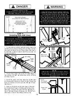
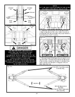
1.
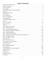
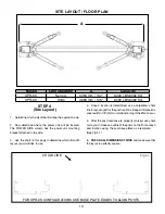
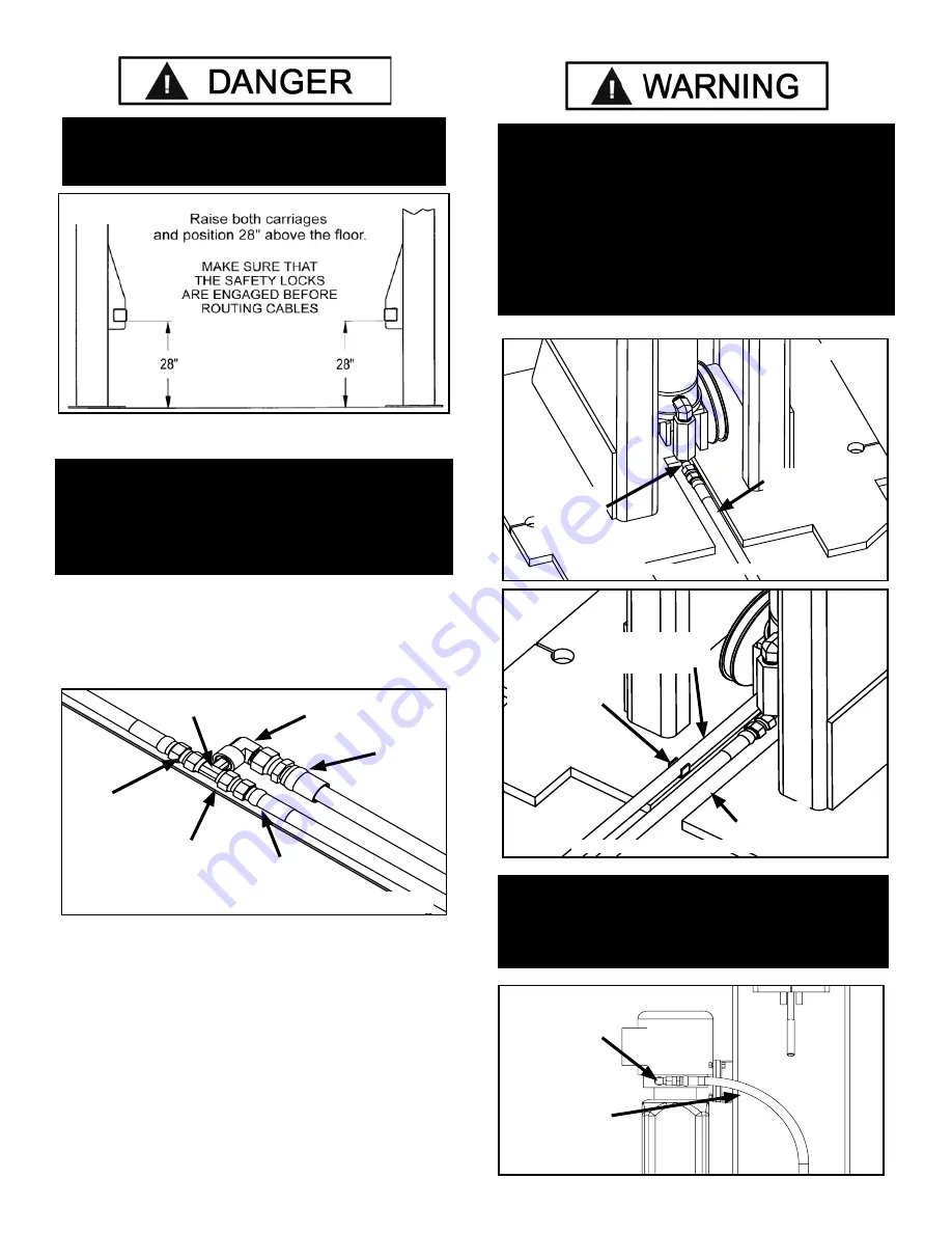
Connect the two cyliinder hydraulic hoses in line to the
tee fitting. Connect the 90° fitting to the tee fitting. Connect
the power unit hose to the 90° fitting. Hoses may have to
be stretched or pulled in order to reach the tee union ref-
erenced on (Fig 9.1)
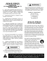
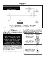
2. Connect the cylinder hoses to the JIC elbow fittings on
the cylinders. DO NOT use teflon tape on the JIC fitting
end. (See Fig 9.2)
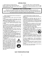
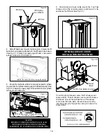
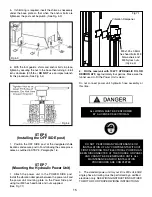
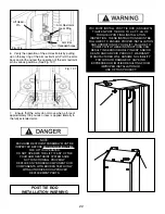
3. Route the power unit hose under the cylinder seat
and the equalizer sheave pin. Route the hose through the
hose clip. Failure to do so may cause damage or injury.
(See Fig 9.3)
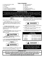
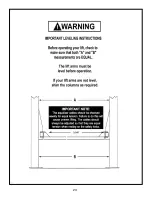
4. Remove the plastic plug from the power unit power
port. Install the 90° power unit fitting with O-ring using
teflon tape. (Connect the power unit hose assembly to
the 90° hydraulic fitting on the power unit. DO NOT use
teflon tape on the JIC hose fittings. (See Fig 9.4)
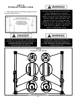
ENSURE THAT BOTH THE
POWER SIDE & OFF SIDE SAFETIES ENGAGE
PROPERLY PRIOR TO LIFT OPERATION.
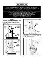
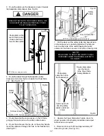
Fig 8.9
Safety
Cable
Power
Side
Hose
Off Side
Hose
90° Fitting
Power
Unit
Hose
Tee Fitting
Fig 9.1
Cylinder
Hose
Fig 9.2
NOTE: Post and lift head cut away for clarity
WHEN ROUTING HYDRAULIC HOSES THROUGH
THE POSTS, ROUTE HOSES THROUGH THE HOSE
CLIPS WELDED ON EACH POST. MAKE SURE
THAT THE HOSE IS CLEAR OF ANY MOVING PARTS.
IT MAY BE NECESSARY TO TIE THE HOSES CLEAR
BY USING NYLON TIE STRAPS OR WIRE. FAILURE
TO KEEP THE HYDRAULIC HOSES CLEAR MAY
RESULT IN THE HYDRAULIC HOSES TO FAIL, WHICH
MAY RESULT IN DAMAGE OR PERSONAL HARM.
Power Unit
Hose Clip
Cylinder
Hose
Fig 9.3
NOTE: Post and lift head cut away for clarity
Power Unit
Hose
NOTE:
POWER PORT LOCATION IN HYDRAULIC POWER
UNIT MAY VARY. CONFIRM THE LOCATION OF THE
POWER PORT ENCLOSED IN THE POWER UNIT
DOCUMENTATION.
Fig 9.4
90° Power
Unit Fitting
Power Unit
Hose
JIC Elbow
Fitting
NOTE:
FOR THE WIDE CONFIGURATION, A 13” EXTENSION
MUST BE INSTALLED TO THE CROSSOVER HOSE. A JIC
TO JIC STRAIGHT FITTING HAS BEEN PROVIDED TO
CONNECT THE CROSSOVER HOSE TO THE EXTENSION
HOSE IN THE PARTS BOX.

