background image

Operation and configuration

23

RCMB423_D00241_01_M_XXEN/12.2016

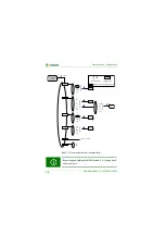
For easier orientation, find an overview of the 

quick menu

 structure below:

Abb. 5.2: Overview operation quick menu

=  Up/Down buttons

=  Setting 

m

ode

=  MENU button

=  Accepted value

=  Ti

m

e the button is pressed

[  ]

s

    2

xx

x

>

m

 A

I   2

30

>

m

 A

I   2

29

Standard
displa

y

s

    2

t on

0

s

    2

t on

1

>

m

 A

I   2

30

s

    2

t on

0

s

    2

t on

1

>

m

 A

I   2

29

[ long ]

[ long ]

[ briefl

y

 ]

[ briefl

y

 ]

[ briefl

y

 ]

>

m

 A

I   2

29

Содержание RCMB423EM

Страница 1: ...Manual EN RCMB423EM Residual current monitor for monitoring AC DC and pulsed DC currents in TN and TT systems Software version D480 V1 01 RCMB423_D00241_01_M_XXEN 12 2016...

Страница 2: ...any Londorfer Strasse 65 35305 Gruenberg Germany Tel 49 6401 807 0 Fax 49 6401 807 259 E Mail info bender de www bender de Bender GmbH Co KG All rights reserved Reprinting only with permission of the...

Страница 3: ...nd storage 8 1 6 Warranty and liability 9 1 7 Disposal 10 2 Safety instructions 11 2 1 General safety instructions 11 2 2 Work activities on electrical installations 11 2 3 Intended use 12 2 4 Informa...

Страница 4: ...4 Parameter settings 27 5 5 Explanatory notes on the setting parameters 28 5 5 1 Menu out 28 5 5 2 Menu t Set delay times 29 5 5 3 Menu SEt 29 5 6 Menu InF Querying device information 29 5 7 Menu HiS...

Страница 5: ...s intended for qualified personnel working in electrical engineering and electronics This signal word indicates that there is a high risk of danger that will result in electrocution or serious injury...

Страница 6: ...Troubleshooting Telephone 49 6401 807 760 Fax 49 6401 807 259 In Germany only 0700BenderHelp Tel and Fax E mail support bender service de 1 2 2 Repair service Repair calibration update and replacement...

Страница 7: ...leshooting of Bender products Analysis of the electrical installation in the building power quality test EMC test thermography Training courses for customers Telephone 49 6401 807 752 762 technical is...

Страница 8: ...dard software as part of de liveries modifications and changes to general delivery conditions for prod ucts and services in the electricalindustry set out by the ZVEI Zentralverband Elektrotechnik und...

Страница 9: ...ing operation and maintenance of the device Unauthorised changes to the device made by parties other than the manufacturer Non observance of technical data Repairs carried out incorrectly and the use...

Страница 10: ...mu nity In Germany these policies are implemented through the Electrical and Electronic Equipment Act ElektroG According to this the following applies Electrical and electronic equipment are not part...

Страница 11: ...regulations must be complied with The European stand ard EN 50110 can be used as a guide Only qualified personnel are permitted to carry out the work necessary to install commission and run a device o...

Страница 12: ...t independent of the nominal voltage and the current of the monitored system The response value I n2 as well as the response delay ton2 can be configured directly from the standard display quick menu...

Страница 13: ...e is indicated on the LC display This way any changes for ex ample when outgoing circuits are connected to the system can be recognised easily If theset responsevaluesare exceeded theresponsedelays to...

Страница 14: ...hours During the self test internal func tional faults will be detected and appear in form of an error code on the dis play The alarm relays are not switched during this test 3 2 3 Self test manual Th...

Страница 15: ...tan tae ton Should the fault no longer persist during the response delay the alarm signal drops out Delay on release toff If the alarm no longer exists during the response delay and the fault memory i...

Страница 16: ...Function 16 RCMB423_D00241_01_M_XXEN 12 2016...

Страница 17: ...ice or system Risk of electrocution due to electric shock Touching live parts of the system carries the risk of An electric shock Damage to the electrical installation Destruction of the device Before...

Страница 18: ...ng clips so that they project beyond the enclosure a second mounting clip is required see ordering information Then fix the device using two M4 screws 2 Wiring Connect the device according to the wiri...

Страница 19: ...eload function with memory off L I I2 Response value I n2 in mA alarm 2 main alarm I1 Response value I n1 in of I n2 alarm 1 prewarning r1 1 r2 2 Alarm relay K1 Alarm relay K2 I Hys Response value hys...

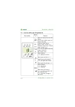
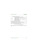
Страница 20: ...hed I n1 LED alarm 2 lit up yellow response value 2 reached I n2 13 mA M 13 m A flow through the measuring current transformer fault memory active T Standard display 2 s display test self test Menu di...

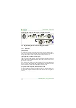
Страница 21: ...set the parameters individually via the full menu refer to Kapitel 5 3 2 The following diagram shows the access conditions for entering the corres ponding setting menu item Abb 5 1 Full and quick menu...

Страница 22: ...ciple the time during which the MENU Enter button is pressed differs briefly 1 s long 2 s very long 5 s Entering changes Modify flashing parameters with the arrow buttons Saving changes Press the MENU...

Страница 23: ...e quick menu structure below Abb 5 2 Overview operation quick menu Up Down buttons Setting mode MENU button Accepted value Time the button is pressed s 2 xx x m A I 2 30 m A I 2 29 Standard display s...

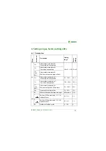
Страница 24: ...etting response values Residual current I2 I n2 AL2 Residual current I1 I n1 AL1 Hysteresis of the response values Hys out Configuring the fault memory and the alarm relays Activate deactivate fault m...

Страница 25: ...Set parameters for device control Selectable parameters for response values Overcurrent operation HI undercurrent operation Lo or window function In Enable or disable password protection change passw...

Страница 26: ...ly By pressing and holding the MENU button 2 s you go back one menu level AL out t SEt InF H S I2 I1 Hys I M 1 2 RI r1 r2 ESC ESC ESC t on 1 t on 2 t t off I12 OFF FAC SYS ESC Software version clr ESC...

Страница 27: ...sponse value I2 flashes in addition the associated response value of 30 mA appears 3 Press the Down button to select the prewarning response value I1 The parameter I1 flashes in addition the associate...

Страница 28: ...ber of reload cycles If faults occur only temporarily but recurrently in the system being monitored with the fault memory M deactivated the alarm relays would switch synchro nously to the error status...

Страница 29: ...generated by the response values I1 and I2 Password protection on OFF If password protection has been enabled on settings can only be made sub ject to the correct password being entered 0 999 Factory...

Страница 30: ...enu HiS Erasable history memory The first alarm value to occur is written to this memory Select the history me mory via the menu HiS Use the Up and Down buttons to view the next dis play If Clr is fla...

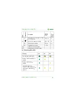
Страница 31: ...alarm I2 Window comparison upper limit I1 Alarm value prewarning I1 Greater than comparison 50 100 50 I1 Alarm value prewarning I1 Less than comparison 100 200 150 I1 win dow Alarm value prewarning I...

Страница 32: ...on off on r2 2 Err Alarm assignment of relay 2 Error message system fault on off on r2 I1 Alarm message prewarning I1 on off off r2 I2 Alarm message main alarm I2 on off on r2 tES Alarm message test o...

Страница 33: ...C Restore factory setting YES no no SYS For Bender Service only 0 999 InF Software version indications HiS Display memory for the first fault Meaning ON AL1 AL2 Error message system fault Response val...

Страница 34: ...Setting ranges factory setting LEDs 34 RCMB423_D00241_01_M_XXEN 12 2016...

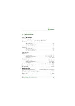
Страница 35: ...60 V DC 24 78 V Operating range of supply voltage Us AC 16 72 V DC 9 6 94 V Frequency rangeUs DC 42 460 Hz RCMB423EM D 2 Supply voltage rangeUs AC DC 100 250 V Operating range of supply voltage Us AC...

Страница 36: ...ating time tae at I n 5 x I n1 2 30 ms Response timetan tan tae ton1 2 Recovery time tb 300 ms Displays memory Display range measured value AC DC 0 6 V Error of measured value indication 17 5 2 digits...

Страница 37: ...Classification of climatic conditions acc to IEC 60721 Stationary use IEC 60721 3 3 3K5 no condensation no formation of ice Transport IEC 60721 3 2 2K3 Long term storage IEC 60721 3 1 1K4 Classificat...

Страница 38: ...operation Position of normal use Display oriented Degree of protection internal components IEC 60529 IP30 Degree of protection terminals IEC 60529 IP20 Enclosure material Polycarbonate Flammability c...

Страница 39: ...A 3 A Rated frequency 0 2000 Hz 0 2000 Hz Supply voltage Us DC 9 6 94 V 16 72 V AC 42 460 Hz DC 70 300 V 70 300 V AC 42 460 Hz Art no B7 push wire terminal B74043038 B94043038 B74043039 B94043039 Abso...

Страница 40: ...WX 100 1 B 9808 0503 WX 250 2 5 B 9808 0504 WX 500 5 B 9808 0505 WX 1000 10 B 9808 0506 Error code Meaning E 01 Fault CT monitoring Action Check transformer connection for short circuit or interrupti...

Страница 41: ...interface 20 H How to use this manual 5 I Installation and connection 17 Intended use 12 L LED alarm 1 lights 20 LED alarm 2 lights 20 M Malfunction 14 Measuring current transformer types 39 Measuring...

Страница 42: ...ent transformer 38 Response delay ton 15 S Selectable parameters for response values 25 Self test automatic 14 Self test manual 14 Service 6 Start up delay t 14 Support 6 T Technical data 35 Test butt...

Страница 43: ......

Страница 44: ...r GmbH Co KG P O Box 1161 35301 Gruenberg Germany Londorfer Strasse 65 35305 Gruenberg Germany Tel 49 6401 807 0 Fax 49 6401 807 259 E Mail info bender de www bender de Photos Bender archives BENDER G...

Отзывы: