7
Wiring
0 to 135
Ω
and 0 to 20 V Phasecut
®
Wiring
1
6
3
24 VAC Transformer
Blk (1) Common
Red (2) Hot +
Pnk (6) Y
Input,
0 to 20V phasecut
Org (5) U
Output, 2 to
10V
…PC
Line
Volts
0 to 20 V Phasecut
Control Signal (–)
(+)
–
1
3
5
4
2
1 Common, Blk
2 + Hot, Red
3 W, Wht
6 R, Pk
7 B, Gy
5 ‘U5’,
Org
…MFT95
Line
Volts
24 VAC Transformer
1
3
5
1 Common, Blk
2 + Hot, Red
3 W, Wht
6 R, Pk
5 B, Gy
6 ‘U5’,
Org
…MFT95
W
R
B
To other
actuators
Resistor Kit No. ZG-R03
Series 90
Controller
Shunting
Resistor
Line
Volts
No. of
actuators Resistance
2
140
Ω
3
71.5
Ω
4
47.5
Ω
5
37.5
Ω
6
28
Ω
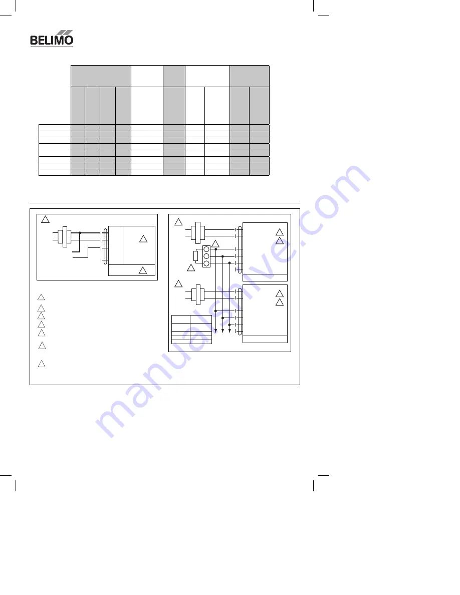
Wiring multiple actuators to a Series 90 controller.
W185
W211
Provide overload protection and disconnect as required.
Actuators may be connected in parallel. Power consumption
and input impedance must be observed.
Actuator may also be powered by 24 VDC.
Actuators and controller must have separate transformers.
Consult controller instruction data for more detailed
installation information.
Resistor value depends on the type of controller and the
number of actuators. No resistor is used for one actuator.
Honeywell resistor kits may also be used.
To reverse control rotation, use the reversing switch.
1
2
3
6
3
4
5
Notes:
Torque
(based on 4 in-lb per
sq. ft)
Running
Time
Power
Supply
Power
Consumption
Feedback
Airside
Products
45 in-lb [5 Nm],
Apprx. 11 sq. ft.
90 in-lb [10 Nm],
Apprx. 22 sq. ft.
180 in-lb [20 Nm],
Apprx. 45 sq. ft.
360 in-lb [40 Nm],
Apprx. 90 sq. ft.
Motor Drive
(Default)
24
VAC +/- 20%,
VDC +/- 15%
VA
r
ating
W
attage running
(holding)
2 tO 10
VDC
(Default)
VDC V
ariable
(0 to 10
VDC)
GMX24-MFT95
150
6.5
4.5 (2.0)
AMX24-MFT95
150
6
4 (1.25)
NMX24-MFT95
150
5.5
3.5 (1.25)
LMX24-MFT95
150
3.5
2 (1.2)
GMX24-PC
150
6.5
4.5 (2.0)
AMX24-PC
150
6
4 (1.25)
NMX24-PC
150
5.5
3.5 (1.25)
LMX24-PC
150
3.5
2 (1.2)


