background image

36

Installation BAT-R

Release 17 12/2020

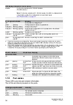
You can order a terminal cable M12, 8-pin, to DB9 as an accessory.

See “Accessories” on page 72.

Note: 

With the point-to-point WLAN line, the following pins are short-circuited 

at both ends:

2 (DTR) + 6 (DSR)

7 (RTS) + 8 (DSR)

1.8.2

USB interface

This interface offers you the ability to connect the storage medium 
AutoConfiguration Adapter ACA21-USB (EEC) / ACA22-USB (EEC). This 
storage medium is used for saving/loading the configuration and diagnostic 
functions, and for loading the software.

The USB interface has the following properties:

Supports the USB master mode

Supports USB 1.1 (data rate max. 12 MBit/s)

Pins of the M12 socket on 
the device

Pin assignment for the connection 
with a cable

Pins of the DB9 plug on 
the external device

Table 5:

Pin assignment for the connection with a cable:
8-pin, „A“-coded M12 plug to DB9 connector

Pins of the M12 socket on 
the device

Pin assignment for the connection 
with a cable

Pins of the M12 socket on 
the device

Table 6:

Pin assignment for the connection with a cable:
8-pin, “A”-coded M12 plug to 8-pin, “A”-coded M12 plug (point-to-point 
WLAN line)

8

2

3

4

7

6

1

5

1
2
3
4
5
6
7
8

5
4
3
2
1
6
7
8

1

8

5

8

2

3

4

7

6

1

5

1
2
3
4
5
6
7
8

1
2
3
4
5
6
7
8

8

2

3

4

7

6

1

5

Содержание Hirschmann OpenBAT BAT-R

Страница 1: ...Installation BAT R Release 17 12 2020 Technical support https hirschmann support belden com User Manual Installation Open Dual Band Industrial Access Point Client Access Bridge OpenBAT Family BAT R ...

Страница 2: ... performance features described here are binding only if they have been expressly agreed when the contract was made This document was produced by Hirschmann Automation and Control GmbH according to the best of the company s knowledge Hirschmann reserves the right to change the contents of this document without prior notice Hirschmann can give no guarantee in respect of the correctness or accuracy ...

Страница 3: ...he characteristic value K 60 V DC 250 V DC 110 V AC 230 V AC 50 Hz 60 Hz 30 1 4 3 Supply voltage with the characteristic value W 24 V DC 30 1 5 Ethernet ports 30 1 5 1 Gigabit combo port 31 1 5 2 10 100 1000 Mbit s twisted pair connection optional 32 1 5 3 Pin assignments 32 1 6 Connections for antennas 33 1 7 Display elements 33 1 7 1 Meaning of the LEDs 33 1 7 2 Device state 33 1 7 3 Port status...

Страница 4: ...tage with the characteristic value K 60 V DC 250 V DC 110 V AC 230 V AC 50 Hz 60 Hz 42 2 5 3 Supply voltage with the characteristic value W 24 V DC 43 2 5 4 Signal contact 44 2 6 Operating the device 44 2 6 1 Connecting the power supply through a terminal block 44 2 6 2 Connecting the power supply through PoE 45 2 7 Connecting data cables 45 2 7 1 Gigabit combo port 46 2 7 2 10 100 1000 Mbit s twi...

Страница 5: ...5 1 IEEE 802 11b 63 10 5 2 IEEE 802 11g 63 10 5 3 IEEE 802 11a 64 10 5 4 IEEE 802 11n 64 10 6 Receiving sensitivity transmit power and data rate of the WLAN module version EWLAN1 for device variants with approval for the 4 9 GHz band Approvals 2 characteristic value P 67 10 6 1 IEEE 802 11a Bandwidth 5 MHz 67 10 6 2 IEEE 802 11a Bandwidth 10 MHz 67 10 6 3 IEEE 802 11a Bandwidth 20 MHz 68 10 7 EMC ...

Страница 6: ...njury or death If this symbol is displayed in addition to a safety instruction of the type Danger or Warning it means that there is a danger of electric shock and failure to observe the instructions will inevitably result in injury This symbol indicates the danger of hot surfaces on the device In connection with safety instructions non observance of the instructions will inevitably result in injur...

Страница 7: ...Installation BAT R Release 17 12 2020 7 NOTICE NOTE provides information about procedures that do not involve the risk of injury ...

Страница 8: ...r malfunction of the device turn off the supply voltage and return the device to the plant for inspection Certified usage Use the product only for the application cases described in the Hirschmann product information including this manual Operate the product only according to the technical specifications See Technical data on page 58 Connect to the product only components suitable for the requirem...

Страница 9: ...cording to IEC EN 62368 1 The device must be installed in either a switch cabinet or other fire enclosure made of metal or plastic with fire protection properties of at least V 1 according to IEC 60695 11 10 and bottom openings 2 mm in diameter if the following conditions are met You connect the device to a power supply that does NOT meet the requirements for Limited Power Source NEC Class 2 or PS...

Страница 10: ...ordance with current standards in safety technology Qualified personnel are aware of the dangers that exist in their work Qualified personnel are familiar with appropriate measures against these hazards in order to reduce the risk for themselves and others Qualified personnel receive training on a regular basis National and international safety regulations Verify that the electrical installation m...

Страница 11: ...tning protection professional installs lightning protection devices for example lightning conductors to protect antennas installed outdoors Ensure that the lightning protection professional takes appropriate lightning protection measures that mitigate the effects of lightning strikes Requirements for connecting electrical wires Before connecting the electrical wires always verify that the requirem...

Страница 12: ... requirements are complied with The power supply complies with the requirements for a safety extra low voltage SELV according to IEC 60950 1 or ES1 according to IEC EN 62368 1 A back up fuse suitable for DC voltage is located in the plus conductor of the power supply The minus conductor is on ground potential Otherwise a back up fuse is also located in the minus conductor Regarding the properties ...

Страница 13: ...d correctly the terminal blocks for the power supply are connected For supply voltage connections with protective conductor connection First connect the protective conductor before connecting the wires for the supply voltage If your device comprises a 2nd supply voltage connection of this type First connect the protective conductor before connecting the wires for the supply voltages ...

Страница 14: ... of the Council on the restriction of the use of certain hazardous substances in electrical and electronic equipment 2014 53 EU RED Directive of the European Parliament and of the council on the harmonization of the laws of the Member States relating to the making available on the market of radio equipment This product may be operated in all EU European Union countries under the condition that it ...

Страница 15: ...Hz band Install an antenna with an antenna gain of at least 3 dBi Applies to the operation of devices with antennas having a gain of more than 8 dBi At temperatures lower than 13 F 25 C a power reduction of 4 dB using a software setting has to be applied This reduction applies in addition to the antenna gain setting Applies to the operation of antennas having a gain of more than 18 dBi For the ope...

Страница 16: ...In addition to the antenna cable supplied the use of the BAT CLB 2 N m f antenna is required See Accessories on page 72 Applies exclusively to BAT R device variants featuring Approvals 2 with characteristic value V SRD The maximum radiated power EIRP is 25 mW according to EN 300 440 Short Range Device ...

Страница 17: ...Agency is required Name and website of the competent authority Bundesnetzagentur www bundesnetzagentur de Ireland IE Frequency range 5725 MHz to 5875 MHz Condition Registration of operational base stations Name and website of the competent authority Commission for Communications Regulation www comreg ie United Kingdom UK Frequency range 5725 MHz to 5850 MHz Condition Light licensing regime Name an...

Страница 18: ...nstructions may cause harmful interference to radio communications However there is no guarantee that interference will not occur in a particular installation If this equipment does cause harmful interference to radio or television reception which can be determined by turning the equipment off and on the user is encouraged to try to correct the interference by one or more of the following measures...

Страница 19: ...e NMB 003 du Canada To reduce potential radio interference to other users the antenna type and its gain should be so chosen that the equivalent isotropically radiated power EIRP is not more than that permitted for successful communication This device has been designed to operate with the antennas listed below in point to multipoint systems and having a maximum gain of 9 dBi The FCC approval is val...

Страница 20: ...he transmit power must be reduced accordingly in the device software You can find step by step instructions for reducing the transmit power in the device software in the Configuring the transmit power for the 4 9 GHz band on page 54 chapter Note for the use in the Japan This note applies to BAT R variants with the characteristic value JP Japan for country approvals that are labeled as follows Cont...

Страница 21: ...rovals This telecommunication equipment complies with the technical requirements of the Telecommunications Regulatory Authority TRA and is labeled as follows Recycling note After usage this device must be disposed of properly as electronic waste in accordance with the current disposal regulations of your county state and country OMAN TRA R 4116 17 D100428 ...

Страница 22: ...ption safety instructions a description of the display and the other information that you need to install the device Documentation mentioned in the User Manual Installation that is not supplied with your device as a printout can be found as PDF files for downloading on the Internet at https www doc hirschmann com ...

Страница 23: ...Installation BAT R Release 17 12 2020 23 Key The symbols used in this manual have the following meanings Listing Work step Subheading ...

Страница 24: ... a bandwidth of up to 450 Mbit s The devices support MIMO Multiple Input Multiple Output and Multipath The bandwidth is increased by using the multipath transmission by means of reflections Each WLAN module has 3 antennas for sending and receiving to ensure stable network coverage with few shadow areas You can choose from a wide range of variants You have the option to set up your device individua...

Страница 25: ... Industrial HiVision V 24 interface locally on the device The device provides you with a large range of functions which the manuals for the operating software inform you about You can download these manuals as PDF files from the Internet on the Hirschmann product pages http www doc hirschmann com The Hirschmann network components help you ensure continuous communication across all levels of the co...

Страница 26: ...C 250 V DC Rated voltage range AC 110 V AC 230 V AC 50 Hz 60 Hz W Rated voltage DC 24 V DC 13 Supply voltage 2 C Rated voltage range DC 24 V DC 48 V DC K Rated voltage range DC 60 V DC 250 V DC Rated voltage range AC 110 V AC 230 V AC 50 Hz 60 Hz W Rated voltage DC 24 V DC 9 Not present 14 Approvals 1 I Substation applications EN 61850 K Rail applications EN 50155 M Motor vehicles applications E t...

Страница 27: ...C S Standard 32 F 140 F 0 C 60 C T Extended 40 F 158 F 40 C 70 C 22 Software option 1 A VPN 5 B VPN 50 C VPN 100 9 Not present 23 Software option 2 9 Not present 24 Software option 3 A AutoWDS D Public Spot P PRP 9 Not present 25 Configuration Z Equipment package 9 Hirschmann standard 26 Device model H Hirschmann standard a Location for which one of the following conditions apply when one operates...

Страница 28: ...K 1 WLAN module 1 3 reverse SMA connection 2 Optional WLAN module 2 3 reverse SMA connection 3 LED display elements for device status 4 Ethernet port 1 Combo port you can use these ports for alternative purposes 4a alternatively depending on device variant Supply voltage with characteristic value C 24 V DC 48 V DC and K 60 V DC 250 V DC 110 V AC 230 V AC 50 Hz 60 Hz RJ45 socket for 10 100 1000 Mbi...

Страница 29: ...tage with characteristic value K 60 V DC 250 V DC 110 V AC 230 V AC 50 Hz 60 Hz 3 pin terminal block 5b Connection for signal contact 1 5c Optional Supply voltage connection 2 Supply voltage with characteristic value C 24 V DC 48 V DC 2 pin terminal block Supply voltage with characteristic value K 60 V DC 250 V DC 110 V AC 230 V AC 50 Hz 60 Hz 3 pin terminal block 5d For devices with 2 supply volt...

Страница 30: ...ply your device with voltage Power supply through a terminal block A 2 pin terminal block is available to supply the device with power Further information Supply voltage with the characteristic value W 24 V DC on page 43 Power supply through PoE Note For devices with 2 WLAN modules the option of suppling power via PoE is unavailable Your device is a PD powered device PSE power sourcing equipment c...

Страница 31: ...x mode 1000 Mbit s full duplex Delivery state Autonegotiation activated The port casing is electrically connected to the front panel The pin assignment corresponds to MDI X When using 10 100 Mbit s the PoE power is supplied via the signal transmitting wire pair phantom voltage or via the free wire pairs spare pair supply 10 100 1000 Mbit s twisted pair port Only device variants featuring supply vo...

Страница 32: ...r port on page 31 1 5 3 Pin assignments RJ45 Pin 10 100 Mbit s 1000 Mbit s PoE MDI mode 1 TX BI_DA Positive VPSE a a Phantom supply 2 TX BI_DA Positive VPSE a 3 RX BI_DB Negative VPSE a 4 BI_DC Positive VPSE b b Spare pair supply 5 BI_DC Positive VPSE b 6 RX BI_DB Negative VPSE a 7 BI_DD Negative VPSE b 8 BI_DD Negative VPSE b MDI X mode 1 RX BI_DB Negative VPSE a 2 RX BI_DB Negative VPSE a 3 TX B...

Страница 33: ... LEDs The following terms describe the behavior of the LEDs Regular flashing the LED switches on and off at regular intervals in the specified sequence e g red off Brief flashing the LED lights up very briefly then remains inactive for a much longer time about 10 as long Inverse flashing the LED remains inactive for a very short time about 10 as long then lights up for a much longer time about 10 ...

Страница 34: ...aling is performed by P1 red green flashing quickly Unprotected configuration as no password or the default password is set a red off flashing quickly Hardware error detected b red green Running light of P1 and P2 A BAT controller WLC with an incompatible protocol is connected green Running light of P1 and P2 Device is searching for a BAT controller WLC WLAN 1 WLAN 2 green red LEDs WLAN mode Meani...

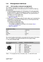
Страница 35: ...point WLAN line by connecting two devices directly via the serial interface You will find more information here User Manual Configuration Guide The manual is available for download on the Internet https www doc hirschmann com table 6 on page 36 The socket housing is electrically connected to the front panel of the device The V 24 interface is electrically insulated from the supply voltage Only use...

Страница 36: ... The USB interface has the following properties Supports the USB master mode Supports USB 1 1 data rate max 12 MBit s Pins of the M12 socket on the device Pin assignment for the connection with a cable Pins of the DB9 plug on the external device Table 5 Pin assignment for the connection with a cable 8 pin A coded M12 plug to DB9 connector Pins of the M12 socket on the device Pin assignment for the...

Страница 37: ...on of setting the signal contact manually using the device management 1 10 Reset button The device has a reset button You will find more information in the User Manual Configuration Guide in the chapter Using the Boot Configurations The manual is available for download on the Internet https www doc hirschmann com Figure Pin Function 1 VCC VBus 2 Data 3 Data 4 Ground GND Table 7 Pin assignment of t...

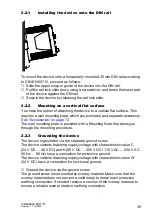
Страница 38: ...ll items named in the section Scope of delivery on page 71 Check the individual parts for transport damage 2 2 Installing and grounding the device WARNING FIRE HAZARD If you connect the device to a power supply that does NOT meet the requirements for Limited Power Source NEC Class 2 or PS2 according to IEC EN 62368 1 and is NOT limited to 100 W output power the device must be installed in either a...

Страница 39: ...ccessories on page 72 The wall mounting plate is provided with a Mounting Note that takes you through the mounting procedure 2 2 3 Grounding the device The device is grounded via the separate ground screw The device variants featuring supply voltage with characteristic value C 24 V DC 48 V DC and K 60 V DC 250 V DC 110 V AC 230 V AC 50 Hz 60 Hz have a connection for protective ground The device va...

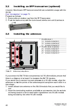
Страница 40: ...etween the BAT R devices If you would like to connect several antennas to a WLAN module align the antennas so that the points of the antennas point away form each other in a star shape Install at least one antenna on the WLAN module that you would like to use Insert the terminating resistors available as accessories into the sockets not being used in order to avoid radio signals from one WLAN modu...

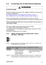
Страница 41: ...ed are complied with See Requirements for connecting electrical wires on page 11 See Requirements for connecting the supply voltage on page 12 Never insert sharp objects small screwdrivers wires etc into the connection terminals for electric conductors and do not touch the terminals Failure to follow this instruction can result in death serious injury or equipment damage Type of the voltages that ...

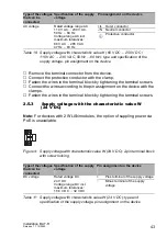
Страница 42: ...0 V AC 50 Hz 60 Hz 3 pin terminal block with screw locking WARNING ELECTRIC SHOCK Install this device only in a switch cabinet or in an operating site with restricted access to which maintenance staff have exclusive access Failure to follow this instruction can result in death serious injury or equipment damage Type of the voltages that can be connected Specification of the supply voltage Pin assi...

Страница 43: ...10 V AC 230 V AC 50 Hz 60 Hz Voltage range AC incl maximum tolerances 88 V AC 265 V AC 47 Hz 63 Hz L Outer conductor N Neutral conductor Protective conductor Type of the voltages that can be connected Specification of the supply voltage Pin assignment on the device DC voltage Rated voltage DC 24 V DC Voltage range DC incl maximum tolerances 16 8 V DC 32 V DC Plus terminal of the supply voltage Min...

Страница 44: ...assignment on the device with the clamps Mount the terminal block on the device using screws 2 6 Operating the device By connecting the supply voltage via a terminal block or a twisted pair cable Power over Ethernet you start the operation of the device 2 6 1 Connecting the power supply through a terminal block Relevant for North America The torque for tightening the supply voltage terminal block ...

Страница 45: ...mission between the buildings When using copper cables provide a sufficient separation between the power supply cables and the data cables Ideally install the cables in separate cable channels Verify that power supply cables and data cables do not run parallel over longer distances To reduce inductive coupling verify that the power supply cables and data cables cross at a 90 angle Use shielded dat...

Страница 46: ...urther information 1000 Mbit s F O port on page 32 Make sure that you connect LH ports exclusively with LH ports SX ports exclusively with SX ports and LX ports exclusively with LX ports Connect the data cables according to your requirements 2 7 2 10 100 1000 Mbit s twisted pair connection optional Further information 10 100 1000 Mbit s twisted pair connection optional on page 32 Connect the data ...

Страница 47: ...ons for configuring IP addresses Input via the V 24 interface Entry via the HiDiscovery protocol in the applications HiDiscovery or Industrial HiVision Configuration via BOOTP Configuration via DHCP Option 82 AutoConfiguration Adapter You will find more information in the User Manual Configuration Guide The manual is available for download on the Internet https www doc hirschmann com ...

Страница 48: ...st time you log on to the device Log on to the device with the default password private The device prompts you to type in a new password Note When you log on with LANconfig the device prompts you to type in a new password before your first configuration change Type in your new password Choose a password that contains at least 8 characters which includes upper case characters lower case characters ...

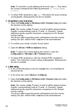
Страница 49: ...n download the LANconfig software from the Hirschmann product pages www hirschmann com Perform the following work steps Command Line Interface CLI To access the possible country settings execute the following command set Setup WLAN Country Note The country setting Europe is valid for all European countries Specific country settings such as France or Germany include additional country specific chan...

Страница 50: ... compliance has been obtained To confirm your choice click the Send button Open the Extras RED compliance dialog Note To check the country setting and correct it open the Configuration Wireless LAN General dialog To obtain RED compliance click the Confirm RED compliance button This makes the country setting unchangeable Subsequently the device restarts LANconfig In the LANconfig device overview hi...

Страница 51: ...he row containing the desired device In the menu bar select Device RED compliance Note To check the country setting and correct it click the No button Then open the Configuration Wireless LAN General dialog To obtain RED compliance click the Yes button This makes the country setting unchangeable Subsequently the device restarts ...

Страница 52: ...ware You can download the LANconfig software from the Hirschmann product pages www hirschmann com In WEBconfig proceed as follows In the menu tree open the Configuration Wireless LAN General dialog In the General tab specify in the General frame the country in which you install the device and click the Send button Note For devices that are operated in the European Union perform the work steps desc...

Страница 53: ...on BAT R Release 17 12 2020 53 Subtract from the antenna gain the attenuation by cables and by surge protection devices Enter the calculated value in the Antenna gain field To save the value click the Send button ...

Страница 54: ...h an antenna gain 9 dBi the transmit power must be reduced accordingly in the device software For more detailed information see the following step by step instructions Open the HiLCOS Menu Tree Setup Interfaces WLAN Radio Settings dialog In the lfc column click the physical WLAN interface to which you connect the antenna In the Radio Band row choose the 5GHz option in the drop down list Subtract t...

Страница 55: ...Installation BAT R Release 17 12 2020 55 To save the value click the Send button ...

Страница 56: ...ts and the switching function depending on the frequency of the switching operations Hirschmann is continually working on improving and developing their software Check regularly whether there is an updated version of the software that provides you with additional benefits You find information and software downloads on the Hirschmann product pages on the Internet http www hirschmann com Depending o...

Страница 57: ...e antennas Disconnect the grounding Insert a screwdriver horizontally below the housing into the locking gate Pull the locking gate down without tilting the screwdriver Lift the bottom of the device away from the DIN rail 9 2 Removing an SFP transceiver optional Pull the SFP transceiver out of the slot by means of the opened lock Close the slot with the protection cap 1 2 ...

Страница 58: ...fer 10 ms at 20 4 V DC Overload current protection on the device Non replaceable fuse Back up fuse for each voltage input when supply is via 2 inputs Nominal rating Characteristic Max 1 5 A slow blow Back up fuse when using 1 voltage inputa Nominal rating Characteristic Max 3 15 A slow blow Back up fuse when installed in a fire enclosure according to IEC 60695 11 10 Nominal rating Characteristic M...

Страница 59: ...w Peak inrush current 14 A Climatic conditions during operation Minimum clearance around the device Top and bottom device side 3 94 in 10 cm Left and right device side 0 79 in 2 cm Ambient air temperaturec Devices with operating temperature characteristic value S Standard 32 F 140 F 0 C 60 C Devices with operating temperature characteristic value E and T extended 40 F 158 F 40 C 70 C d Devices wit...

Страница 60: ...30 V DC SELV according to IEC 60950 1 or ES1 according to IEC EN 62368 1 Pollution degree 2 Protection classes Laser protection Class 1 in compliance with IEC 60825 1 Degree of protection IP20 a As an alternative to the back up fuse is possible Supply voltage based on Limited Power Source NEC Class 2 or PS2 according to IEC EN 62368 1 AND maximum output power 100 W b As an alternative to the back ...

Страница 61: ... of device variants featuring supply voltage with characteristic value C 24 V DC 48 V DC or K 60 V DC 250 V DC 110 V AC 230 V AC 50 Hz 60 Hz See table 3 on page 26 Note figure without connections 145 mm 150 6 mm 120 8 mm 136 4 mm 5 93 in 5 71 in 4 76 in 5 37 in ...

Страница 62: ... of the type TKIP and WEP the device falls back on IEEE 802 11b g or IEEE 802 11a b With encryptions of the type TKIP and WEP the device falls back on IEEE 802 11b g or IEEE 802 11a c With encryptions of the type TKIP and WEP the device falls back on IEEE 802 11b g or IEEE 802 11a d With encryptions of the type TKIP and WEP the device falls back on IEEE 802 11b g or IEEE 802 11a Frequency range Su...

Страница 63: ...cal transmit power was reduced as follows to be compliant with FCC regulations for all modulations Channels 4 7 and 8 Reduction by 3 dB Channels 2 3 5 6 and 9 Reduction by 4 dB Channel 10 Reduction by 5 dB Channel 1 Reduction by 6 dB Channel 11 Reduction by 8 dB Typical receiving sensitivity 1 Mbit s 19 dBm 94 dBm 11 Mbit s 19 dBm 94 dBm Table 12 IEEE 802 11b Frequency range 2 412 GHz to 2 472 GHz...

Страница 64: ... with FCC regulations for all modulations Typical receiving sensitivity 6 Mbit s 16 dBm 93 dBm 9 Mbit s 16 dBm 93 dBm 12 Mbit s 16 dBm 93 dBm 18 Mbit s 16 dBm 91 dBm 24 Mbit s 16 dBm 88 dBm 36 Mbit s 15 dBm 84 dBm 48 Mbit s 13 dBm 80 dBm 54 Mbit s 12 dBm 79 dBm Table 14 IEEE 802 11a Frequency range 5 180 GHz to 5 825 GHz for FCC 5 180 GHz to 5 240 GHz and 5 745 GHz to 5 825 GHz IEEE 802 11n Freque...

Страница 65: ... 4 dB Channel 10 Reduction by 5 dB Channel 1 Reduction by 6 dB Channel 11 Reduction by 8 dB IEEE 802 11n Frequency range 5 180 GHz to 5 825 GHz for FCC 5 180 GHz to 5 240 GHz and 5 745 GHz to 5 825 GHz Coding Typical transmit powera Typical receiving sensitivity MCS 0 17 dBm 92 dBm MCS 1 17 dBm 91 dBm MCS 2 17 dBm 89 dBm MCS 3 17 dBm 84 dBm MCS 4 17 dBm 81 dBm MCS 5 15 dBm 77 dBm Table 16 IEEE 802...

Страница 66: ...dBm 84 dBm MCS 20 16 dBm 81 dBm MCS 21 15 dBm 77 dBm MCS 22 14 dBm 75 dBm MCS 23 14 dBm 73 dBm a The typical transmit power was reduced by 6 dB on channels 36 40 44 48 and 149 to be compliant with FCC regulations for all modulations IEEE 802 11n Frequency range 5 180 GHz to 5 825 GHz for FCC 5 180 GHz to 5 240 GHz and 5 745 GHz to 5 825 GHz Coding Typical transmit powera Typical receiving sensitiv...

Страница 67: ...ty of the overall product Depending on the settings the module automatically reduces the data rate and transmit power according to FCC 47CFR Part 90 Subpart Y 10 6 1 IEEE 802 11a Bandwidth 5 MHz 10 6 2 IEEE 802 11a Bandwidth 10 MHz IEEE 802 11a Frequency range 4 940 GHz to 4 990 GHz Bandwidth 5 MHz Data rate Typical transmit power 1 5 Mbit s 13 dBm 2 25 Mbit s 13 dBm 3 Mbit s 13 dBm 4 5 Mbit s 13 ...

Страница 68: ...s 14 dBm 36 Mbit s 13 dBm 48 Mbit s 13 dBm 54 Mbit s 12 dBm Table 19 IEEE 802 11a Frequency range 4 940 GHz to 4 990 GHz Bandwidth 20 MHz Channels 20 26 EMC interference immunity EN 61000 4 2 Electrostatic discharge Contact discharge test level 4 8 kV Air discharge test level 4 15 kV EN 61000 4 3 Electromagnetic field 80 MHz 1000 MHz 20 V m 1400 MHz 2700 MHz 10 V m IEEE 802 11a Frequency range 4 9...

Страница 69: ...EN 61000 4 6 Conducted interference voltages test level 3 150 kHz 80 MHz 10 V EN 61000 4 9 Pulse magnetic fields 300 A m EMC interference emission EN 55032 Class B FCC 47 CFR Part 15 Class A Immunity Vibration IEC 60068 2 6 Test FC test level according to IEC 61131 2 Shock IEC 60068 2 27 Test Ea test level in accordance with IEC 61131 2 EN 50155 Product code M SFP Wave length Fiber System attenuat...

Страница 70: ... c With F O adapter compliant with IEEE 802 3 2002 Clause 38 single mode fiber offset launch mode conditioning patch cord d With F O adapter compliant with IEEE 802 3 2002 Clause 38 single mode fiber offset launch mode conditioning patch cord e Including 2 5 dB system reserve when compliance with the fiber data is observed 10 100 1000 Mbit s twisted pair port Length of a twisted pair segment max 3...

Страница 71: ...ck for signal contact exclusively for device variants featuring supply voltage with characteristic value C 24 V DC 48 V DC K 60 V DC 250 V DC 110 V AC 230 V AC 50 Hz 60 Hz or W 24 V DC 2 premounted 50 Ω terminating resistor for sealing unused antenna connections exclusively for device variants with 1 wireless module 3 premounted 50 Ω terminating resistor for sealing unused antenna connections excl...

Страница 72: ...in terminal block for signal contact 50 pieces 943 845 010 50 Ω terminating resistors for sealing unused antenna connections N 10 pieces 942 117 001 Antenna cable BAT CLB 2 N m f 943 903 514 AutoConfiguration AdapterACA21 USB EEC 943 271 003 AutoConfiguration Adapter ACA22 USB EEC 942 124 001 For device variants featuring supply voltage with characteristic value C 24 V DC 48 V DC or W 24 V DC 2 pi...

Страница 73: ...ailway applications Fire protection on railway vehicles Part 1 General EN 45545 2 Railway applications Fire protection on railway vehicles Part 2 Requirements for fire behavior of materials and components EN 50155 Railway applications Electronic equipment used on rolling stock EN 55032 Electromagnetic compatibility of multimedia equipment Emission Requirements EN 60079 0 Explosive atmospheres Part...

Страница 74: ...lease 17 12 2020 The device has an approval based on a specific standard exclusively if the approval indicator appears on the device casing The device generally fulfills the technical standards named in their current versions ...

Страница 75: ...Competence Center is ahead of its competitors on three counts with its complete range of innovative services Consulting incorporates comprehensive technical advice from system evaluation through network planning to project planning Training offers you an introduction to the basics product briefing and user training with certification You find the training courses on technology and products current...

Страница 76: ......

Отзывы: