AIRBLADE® DRYER
Mix and Match
68
Belanger, Inc. * 1001 Doheny Ct. * Northville, MI 48167 * Ph (810) 349-7010 * Fax (810) 380-9681
1MANUL011
Installation
6-Nozzle Frame Assembly: Wall Mounted
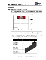
32) Record the distance from the mark on the head beam to the center of the housings. If the
distance from the mark on the head beam to the center of the housings (where they but
up at) is less than the amount of travel you have in that direction inside of the wall mount
bracket you can side shift the head beam in that direction.
33) If the distance is greater, you will have to loosen the AirBlade® housing brackets and
slide them over using the supplied housing lift assembly by following the steps below.
Note:
If you need to shift the AirBlade® housings to the left start with the left housing since
there is only one Lift Assembly supplied.
•
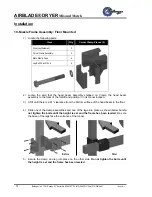
Locate the supplied Housing Lift Assembly as shown below.
•
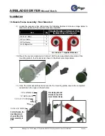
Remove the two fasteners from the upper AirBlade® Housing Weldment Assembly
and install the Housing Lift Assembly as shown below.
•
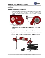
Position one of the forks into place as shown below.
Top View
of Forklift
Fork butts up here


