


High resolution is only available when the
transmitter is displaying temperature in
o
C. When
o
F
is selected the resolution is always one degree
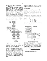
To check or change the display resolution select
'rESn' from the sub-menu and press
P
to reveal the
current setting. The setting may be changed by
pressing the
Up
or
Down
button. When the required
resolution has been selected, press
E
to return to
the sub-menu.
Display Resolution
Type Low (Lo) High (Hi)
E
1
o
C
0.1
o
C
J
1
o
C
0.1
o
C
K
1
o
C
0.2
o
C *
N
1
o
C
0.2
o
C *
R
1
o
C
0.4
o
C *
T
1
o
C
0.1
o
C
Pallaplat
1
o
C
0.2
o
C *
* Worst case resolution figures are quoted, at
most temperatures resolution will be greater.
6.3.4 Cold junction compensation 'CJC'
The temperature of the transmitter input terminals,
which is the thermocouple cold junction, is
measured and added to the output from the
thermocouple so that the transmitter displays and
transmits the temperature relative to zero degrees
centigrade or Fahrenheit. If cold junction
compensation is not required, e.g. for differential
measurement with two thermocouples, this function
enables the cold junction compensation to be turned
off.
To turn the cold junction compensation on or off
select 'CJC' from the sub-menu and press
P
to
reveal the current status. The setting may be
changed by pressing the
Up
or
Down
button. When
set as required press
E
to return to the sub-menu.
6.3.5 Input open circuit drive 'burn'
If the thermocouple fails and becomes open circuit,
the transmitter can be conditioned to drive the
display and the 4/20mA output current up or down
into a safe condition. Alternatively the drive may be
turned off which will result in the display and the
4/20mA output current drifting towards zero when
the thermocouple breaks.
To check or change the input open circuit drive
select 'burn' from the sub-menu and press
P
to
reveal the current setting. The setting may be
changed by pressing the
Up
or
Down
button. When
the required setting has been selected, press
E
to
return to the sub-menu.
6.4 For resistance thermometer inputs
6.4.1 Types of resistance thermometer 'tYPE'
The transmitter may be conditioned to accept
3-wire, 4-wire or differential Pt100 resistance
thermometers.
After selecting resistance thermometer input from
the 'InPut' sub-menu, press
P
to reveal the 'tYPE'
sub-menu. Press
P
again to display the current
type of resistance thermometer which may be
changed by scrolling through the menu using the
Up
or
Down
buttons. When the required type is
displayed, press
E
to return to the sub-menu.
6.4.2 Display units 'dEg'
The transmitter display may be in degrees
centigrade or Fahrenheit. To check or change the
display units select 'dEg' from the sub-menu and
press
P
to reveal the current setting. The setting
may be changed by pressing the
Up
or
Down
button. When the required unit is displayed, press
E
to return to the sub-menu.
6.4.3 Display resolution 'rESn'
The output of the resistance thermometer can be
displayed with high or low resolution as shown
below. Low resolution can improve the readability
of a noisy or rapidly changing display, but does not
degrade the performance of the 4/20mA analogue
output. High resolution is only available when the
transmitter is displaying temperature in
o
C. When
o
F
is selected the resolution is always one degree.
To check or change the display resolution select
'rESn' from the sub-menu and press
P
to reveal the
current setting. The setting may be changed by
pressing the
Up
or
Down
button. When the required
resolution has been selected, press
E
to return to
the sub-menu.
Display Resolution
Low High
1
o
C
0.1
o
C
6.5 For Voltage Inputs
When the transmitter is conditioned for a voltage
input both the input voltage range and the
corresponding display must be programmed.
6.5.1 Position of display decimal point 'd.P.
'
A dummy decimal point can be positioned between
any of the display digits or it may be absent.
14


