


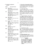


11.4 Adjusting the alarm setpoints from the
display mode.
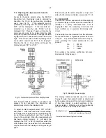
Access to the alarm setpoint when the BA378C
transmitter is in the display mode is obtained by
operating the
P
and
Up
push-buttons simultane-
ously - see Fig 14. If the setpoints are not
protected by a security code the alarm setpoint one
'SP1' will be displayed. If the setpoints are
protected by a security code, 'COdE' will be
displayed first. Pressing
P
again will enable the
alarm security code to be entered digit by digit
using the
Up
and
Down
buttons to change the flash-
ing digit, and the
P
push-button to move to the next
digit. If the correct code is entered pressing
E
will
cause alarm setpoint one 'SP1' to be displayed.
Pressing the
Up
or
Down
button will toggle the
display between 'SP1' and 'SP2'.
Fig 14 Setpoint adjustment from display mode
If an incorrect code is entered, or a button is not
pressed for ten seconds, the transmitter will
automatically return to the display mode.
To adjust an alarm setpoint select 'SP1' or 'SP2'
and press
P
which will reveal the current setting.
Each digit of the setpoint may be adjusted using the
Up
and
Down
push-buttons, and the
P
button to
move to the next digit. When the required setpoint
has been entered, pressing
E
will return the
display to the 'SP1' or 'SP2' prompt from which the
other setpoint may be selected, or the transmitter
may be returned to the display mode by pressing
E
again.
Direct access to the alarm setpoints is only avail-
able when the menu is enabled - see section 11.3.8
12. BACKLIGHT
The BA378C can be supplied with LED backlighting
to improve display contrast when the transmitter is
installed in a poorly illuminated area. This is
segregated from the measuring circuit and has
been certified as a separate intrinsically safe
circuit.
The backlight must be powered from the safe area
via a Zener barrier or a galvanic isolator as shown
in Fig 15. Any certified EEx ia IIC device may be
used, providing the output parameters do not
exceed:
Uo
=
30V dc
Io
=
159mA
Po
=
0.85W
For guidance, the system certificates list some
devices which may be used.
Fig 15 Backlight power supply
The display brilliance depends upon the current
flowing through the backlight which is determined
by the supply voltage and the end-to-end resistance
of the Zener barrier or output resistance of the
galvanic isolator. Brilliance will not be significantly
reduced until the current falls below 20mA.
Backlight current = Vsupply -18
End-to-end resistance of barrier
#
# or output resistance of galvanic isolator
27