background image

25

9.4.10  Alarm silence time:   SiL

This function is primarily intended for use in small
installations  where  the  alarm  output  directly
operates an alarm annunciator such as a sounder
or beacon.  When the alarm silence time, which is
adjustable  between  0  and  3600  seconds  in  1
second increments, is set to any figure other than
zero, the 

P

 push button becomes an alarm accept

button.   After an alarm has occurred, operating the

P

 button will cause the alarm output to revert to the

non-alarm  condition  for  the  programmed  alarm
silence time.  If the alarm condition still exists at
the end of the silence time, the alarm output will be
reactivated.  During the silence time the indicator
alarm annunciator will flash until the silence time
expires or the alarm is cleared. 

If the ‘FLSH’ function, which flashes the indicator
display when an alarm occurs has been enabled,
it  will  only  function  when  the  alarm  output  is
activated, not during the silence time.  See section
9.4.11

To adjust the alarm silence time select 'SiL' from
the alarm configuration menu and press  

P

 which

will reveal the existing silence time.  The flashing
digit of the silence time can be adjusted using the

 and 

 push buttons, and the 

P

 button to move

control  to  the  other  digits.    When  the  required
silence time has been entered press 

E


to return to

the alarm menu.

9.4.11 Flash display when alarm occurs


‘FLSH’

In addition to the two alarm annunciators on the
top left hand corner of the indicator display which
show  the  status  of  both  alarms,  this  function
provides an even more conspicuous indication that
an alarm condition has occurred.    

When enabled, the function alternates the indicator
display between the numerical value and the alarm
reference, ‘ALr1’ or ‘ALr2’, when the alarm output
is activated.  If both alarm outputs are activated,
the alarm references are displayed in sequence.

To  enable  or  disable  the  function  select  'FLSH'
from the alarm menu and press 

P

 which will reveal

the current setting ‘on’ or ‘oFF’.  The function can
changed by pressing the 

 or 

 button followed

by the 

E

 button to return to the alarm menu.

9.4.12 Access setpoint in display mode:  ACSP

This function enables a separate menu providing
access  to  the  alarm  setpoints  from  the  display
mode  by  simultaneously  operating  the  

P

 and  

push buttons.  An operator can therefore adjust the
alarm  setpoints  without  having  access  to  the
indicator  configuration  menu.    Protection  against
accidental  adjustment  of  the  setpoints  when  the

indicator is in the display mode is provided by a
separate security code.

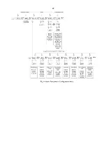
This direct setpoint access menu is enabled and
the  separate  security  code  entered  from  the
'ACSP' function in the alarm configuration menu as
shown in Fig 12.  To change the menu parameters
select  'ACSP'  from  the  configuration  menu  and
press  

P


which  will  display  the  enable  prompt

'EnbL'.  Press 

P

 again to reveal if the direct access

menu  is  'on'  or  'oFF'.    The  

 or  

 button  will

toggle the display between the two conditions.  

If  'oFF'  is  selected,  the  operator  will  not  have
access  to  the  setpoints  from  the  display  mode.
Return to the 'ACSP' prompt in the main menu by
pressing


E

 twice.  

If  'on'  is  selected,  the  operator  will  have  direct
access  to  the  alarm  setpoints  from  the  display
mode via a separate optional security code.   To
define this four digit security code press 

P

 to return

to the 'Enbl' prompt followed by the 

 or 

 button

to  select  the  access  code  prompt  'ACCd'.
Pressing  

P


will  reveal  the  current  security  code.

Each  digit  of  the  code  may  be  changed  by
operating the 

 and 

 push buttons, and the  

P

button to move control to the next digit.  When the
required code has been entered, press 

E

 twice to

return  to  the  'ACSP'  prompt  in  the  configuration
menu.

Default  code  0000  will  disable  the  security  code
allowing  direct  access  to  the  setpoints  in  the
display  mode  by  pressing  the


P


and  

 buttons

simultaneously.  Unless otherwise requested new
instruments  with  alarms  are  supplied  with  this
function  disabled  and  the  security  code  set  to
0000.

9.4.13  Adjusting alarm setpoints from the
            display mode

Access  to  the  alarm  setpoints  from  the  indicator
display mode is obtained by operating the 

P

 and 

push buttons simultaneously as shown in Fig 15.  If
the setpoints are not protected by a security code
the alarm setpoint prompt 'SP1' will be displayed.
If the setpoints are protected by a security code,
'Code' will be displayed first.  Pressing 

P

 again will

enable the alarm security code to be entered digit
by digit using the 

 and 

 buttons to change the

flashing  digit,  and  the  

P

  push  button  to  move

control  to  the  next  digit.    If  the  correct  code  is
entered  pressing  

E


will  cause  alarm  setpoint

prompt 'SP1' to be displayed.  Pressing the 

 or

 button will toggle the display between the two

alarm setpoint prompts 'SP1' and 'SP2'.

If an incorrect security code is entered, or a button
is not pressed within twenty seconds, the indicator
will automatically return to the display mode.

Содержание BA307NE

Страница 1: ...Issue 3 1st Novemeber 2017 BA307NE BA327NE Ex nA Ex tc loop powered panel mounting indicators Issue 3...

Страница 2: ...figuration 8 Maintenance 8 1 Fault finding during commissioning 8 2 Fault finding after commissioning 8 3 Servicing 8 4 Routine maintenance 8 5 Guarantee 8 6 Customer comments 9 Accessories 9 1 Scale...

Страница 3: ...European ATEX Directive 94 9 EC The certificate number has an X suffix indicating that the two indicators are subject to special condition for safe use For installations in Zone 2 the panel enclosure...

Страница 4: ...both instruments with a common Type Examination Certificate number ITS14ATEX48028X This has been used to confirm compliance with the European ATEX Directive for Group II Category 3GD equipment The in...

Страница 5: ...roups Group A propane Group B ethylene Group C hydrogen In gases that may safely be used with equipment having a temperature classification of T1 450o C T2 300o C T3 200o C T4 135o C T5 100o C At ambi...

Страница 6: ...ea should be individually fused and contain a means of isolation These two requirements are frequently satisfied by using switch fuse holders with easily removable fuses which can be extracted to achi...

Страница 7: ...is a satisfactory method at the low voltages and currents common in instrumentation systems Clear identification of and easy access to the means of isolation is essential for their effective use It i...

Страница 8: ...el enclosure cut out dimensions Fig 4 Dimensions 5 2 Installation Procedure a Cut the aperture specified in Fig 4 in the panel enclosure Ensure that the edges of aperture are de burred b Inspect the i...

Страница 9: ...ard showing the requested units of measurement if this information is not supplied when the indicator is ordered a blank card will be fitted A pack of self adhesive scale cards printed with common uni...

Страница 10: ...10...

Страница 11: ...uration BA307NE BA327NE Access code CodE 0000 0000 Function FunC Linear Linear Display at 4mA Zero 0 0 0 00 Display at 20mA SPAn 100 0 100 00 Resolution rESn 1 digit 1 digit Bargraph start BarLo 0 00...

Страница 12: ...in 16 segment adjustable lineariser To reveal the existing indicator function select FunC from the configuration menu and press P If the function is set as required press E to return to the menu or pr...

Страница 13: ...tween the two currents is greater than 4mA If these conditions are not complied with the indicator displays FaiL and aborts the calibration c If the zero current is greater than the span current the i...

Страница 14: ...rompt in the configuration menu 6 10 Security code CodE Access to the instrument configuration menu may be protected by a four digit security code which must be entered to gain access New instruments...

Страница 15: ...e This method allows direct calibration of the lineariser with an external current source and is the preferred method when traceability is required If the exact system non linearity is unknown this me...

Страница 16: ...16...

Страница 17: ...to the required value before the P button is operated to enter the required indicator display Error message If during calibration the indicator displays a FAiL error message the current at which the s...

Страница 18: ...oints has been defined and then return to the in sub function by pressing the E button The corresponding indicator display at each of the break points can now be defined using the diSP sub function Us...

Страница 19: ...rior of the instrument with dust or moisture Some end users may prefer not to permit live maintenance to minimise risk ENSURE PLANT SAFETY BEFORE STARTING MAINTENANCE Live maintenance within the hazar...

Страница 20: ...the enclosure panel being distorted or creeping when the indicator panel clamps are tightened and ensures that the joint between the indicator and the panel enclosure in which it is mounted remains se...

Страница 21: ...ed in Zone 2 is displaying the output from an Flameproof Ex d 2 wire transmitter located in Zone 1 Alarm 1 is switching an Ex e sounder in Zone 1 and alarm 2 is switching a sounder located in the safe...

Страница 22: ...22...

Страница 23: ...ndicator display equals the setpoint See section 9 4 5 Hi Lo Alarm function Defines the alarm function as High or Low See section 9 4 6 no nC Normally open or normally closed output Sets the alarm out...

Страница 24: ...r fail safe operation both alarm outputs should be conditioned to be open in the alarm condition nC To check or change the alarm output status select no nC from the alarm configuration menu and press...

Страница 25: ...ving access to the indicator configuration menu Protection against accidental adjustment of the setpoints when the indicator is in the display mode is provided by a separate security code This direct...

Страница 26: ...int plus the displayed value to be represented or a low and a high setpoint plus the displayed value to be represented by the bargraph as shown in Fig 16 Fig 16 Displayed value and setpoints on bargra...

Страница 27: ...o or greater than 9V At lower supply voltages the backlight will continue to function but with reduced brilliance and will draw less current The ATEX certificate therefore only specifies the maximum s...

Страница 28: ...re four design requirements 1 The indicator should be installed generally as shown in section 5 and Fig 20 2 The certificate specifies that the indicator should be connected to a limited energy 4 20mA...

Страница 29: ...Fig 21 2 The four vents at the rear of the indicator enclosure shown in Fig 22 must not be obstructed 3 The certificate specifies that the indicator should be connected to a limited energy 4 20mA circ...

Страница 30: ...ne 22 The panel enclosure containing the indicator should be located where the minimum amount of dust will accumulate on them and the installation should be as specified in section 5 of this instructi...

Страница 31: ...X 4 ETL cETL certification for installations in USA and Canada A4 0 cETL Mark For installations in the USA and Canada the BA307NE and BA327NE indicators have ETL and cETL Ex nA and Ex tc approval Cont...

Отзывы: