background image

6

4.  SYSTEM DESIGN FOR USE IN ZONE 2 GAS
     HAZARDOUS AREAS.

4.1 Transmitter loops

When correctly mounted in Zone 2 both indicators
may  be  connected  in  series  with  almost  any
4/20mA current  loop  with  apparatus  in  the  safe
area,  or  with  Ex n, Ex e, Ex p or  Ex d  protected
apparatus located in Zones 1 or 2.  The indicators
are transparent to HART 

®

 signals.

Because  the  BA307NE  and  BA327NE  are  not
certified  intrinsically  safe  they  should  not  be
connected to an intrinsically safe system.

There are four design requirements:

1. The  indicator  must  be  installed  in  a  panel

enclosure  complying  with  the  requirements
for Ex n protection as shown in section 5 of
this manual.

2. The  certificate  specifies  that  the  indicator

should  be  connected  to  a  

limited  energy

4/20mA  circuit  having  a  maximum  output
current  of  200mA.    A


low  voltage  supply,

usually 24V,  that is safe in normal operation
and  suitable  for  live  connection  i.e.  CE
marked, is usually considered acceptable. 

3. Wiring  must  comply  with  Clause  9  of

BS EN 60079-14.

4. The  loop  must  be  able  to  tolerate  the

additional  1.2V  required  to  operate  the
indicator.    This  increases  to  5.0V  if  the
indicator  is  fitted  with  an  optional  backlight
which is loop powered.  See 9.5.1

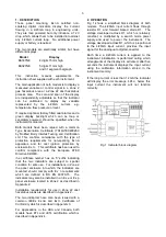
Figs  2  illustrate  a  typical  application  in  which  a
BA307NE  or  BA327NE  located  in  Zone  2  is
connected in series with a 2-wire Ex d transmitter
located  in  Zone  1.      BEKA  Application  Guide
AG310,  which  can  be  downloaded  from
www.beka.co.uk, contains examples of other Ex n
applications.

Fig 2  Typical Zone 2 transmitter loop

To  comply  with  the  requirements  of
BS  EN  60079:

14:2008  Electrical  installations

design, selection and erection

, each of the wires

entering the hazardous area should be individually
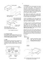
fused and contain a means of isolation.  These two
requirements  are  frequently  satisfied  by  using
switch  fuse  holders  with  easily  removable  fuses
which  can  be  extracted  to  achieve  isolation  as
shown in Fig 20.  This is a satisfactory method at
the  low  voltages  and  currents  common  in
instrumentation  systems.  Clear  identification  of,
and  easy  access  to  the  means  of  isolation  is
essential for their effective use. It is also necessary
to ensure that the maintenance procedure makes
sure that unauthorised re-closure of the switches
does not occur. It is not considered necessary to
have a means of isolation or electrical protection
for the screen.   

For  some  applications  Ex nA  instrumentation
energised  by  a  current  limited  power  supply  or
instrument  that  can  be  switched  off,  is  often
considered  adequate  and  to  comply  with  the
requirements of the standard.

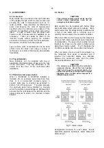
4.2  Remote indication

The  BA307NE  and  the  BA327NE  may  also  be
driven directly from a safe area instrument with a
4/20mA output to provide a remote display within a
Zone 2 hazardous area.   

There are four design requirements:

1. The  indicator  must  be  installed  in  a  panel

enclosure  complying  with  the  requirements
for Ex n protection as shown in section 5 of
this manual.

2.

The  certificates  specify  that  the  indicator
should  be  connected  to  a  

limited  energy

4/20mA  circuit  having  a  maximum  output
current of 200mA.  An instrument located in
the safe area that is safe in normal operation
and  has  a  4/20mA output  suitable  for  live
connection  i.e.  CE  marked,  is  usually
considered acceptable. 

3. Wiring  must  comply  with  Clause  9  of

BS EN 60079-14:2008.

4. The  output  from  the  safe  area  4/20mA

instrument must be able to supply the 1.2V
required  to  operate  the  indicator.      This
increases to 5.0V if the indicator includes an
optional  backlight  which  is  loop  powered.
See 9.4.1

Fig 3 shows a typical application.

Содержание BA307NE

Страница 1: ...Issue 3 1st Novemeber 2017 BA307NE BA327NE Ex nA Ex tc loop powered panel mounting indicators Issue 3...

Страница 2: ...figuration 8 Maintenance 8 1 Fault finding during commissioning 8 2 Fault finding after commissioning 8 3 Servicing 8 4 Routine maintenance 8 5 Guarantee 8 6 Customer comments 9 Accessories 9 1 Scale...

Страница 3: ...European ATEX Directive 94 9 EC The certificate number has an X suffix indicating that the two indicators are subject to special condition for safe use For installations in Zone 2 the panel enclosure...

Страница 4: ...both instruments with a common Type Examination Certificate number ITS14ATEX48028X This has been used to confirm compliance with the European ATEX Directive for Group II Category 3GD equipment The in...

Страница 5: ...roups Group A propane Group B ethylene Group C hydrogen In gases that may safely be used with equipment having a temperature classification of T1 450o C T2 300o C T3 200o C T4 135o C T5 100o C At ambi...

Страница 6: ...ea should be individually fused and contain a means of isolation These two requirements are frequently satisfied by using switch fuse holders with easily removable fuses which can be extracted to achi...

Страница 7: ...is a satisfactory method at the low voltages and currents common in instrumentation systems Clear identification of and easy access to the means of isolation is essential for their effective use It i...

Страница 8: ...el enclosure cut out dimensions Fig 4 Dimensions 5 2 Installation Procedure a Cut the aperture specified in Fig 4 in the panel enclosure Ensure that the edges of aperture are de burred b Inspect the i...

Страница 9: ...ard showing the requested units of measurement if this information is not supplied when the indicator is ordered a blank card will be fitted A pack of self adhesive scale cards printed with common uni...

Страница 10: ...10...

Страница 11: ...uration BA307NE BA327NE Access code CodE 0000 0000 Function FunC Linear Linear Display at 4mA Zero 0 0 0 00 Display at 20mA SPAn 100 0 100 00 Resolution rESn 1 digit 1 digit Bargraph start BarLo 0 00...

Страница 12: ...in 16 segment adjustable lineariser To reveal the existing indicator function select FunC from the configuration menu and press P If the function is set as required press E to return to the menu or pr...

Страница 13: ...tween the two currents is greater than 4mA If these conditions are not complied with the indicator displays FaiL and aborts the calibration c If the zero current is greater than the span current the i...

Страница 14: ...rompt in the configuration menu 6 10 Security code CodE Access to the instrument configuration menu may be protected by a four digit security code which must be entered to gain access New instruments...

Страница 15: ...e This method allows direct calibration of the lineariser with an external current source and is the preferred method when traceability is required If the exact system non linearity is unknown this me...

Страница 16: ...16...

Страница 17: ...to the required value before the P button is operated to enter the required indicator display Error message If during calibration the indicator displays a FAiL error message the current at which the s...

Страница 18: ...oints has been defined and then return to the in sub function by pressing the E button The corresponding indicator display at each of the break points can now be defined using the diSP sub function Us...

Страница 19: ...rior of the instrument with dust or moisture Some end users may prefer not to permit live maintenance to minimise risk ENSURE PLANT SAFETY BEFORE STARTING MAINTENANCE Live maintenance within the hazar...

Страница 20: ...the enclosure panel being distorted or creeping when the indicator panel clamps are tightened and ensures that the joint between the indicator and the panel enclosure in which it is mounted remains se...

Страница 21: ...ed in Zone 2 is displaying the output from an Flameproof Ex d 2 wire transmitter located in Zone 1 Alarm 1 is switching an Ex e sounder in Zone 1 and alarm 2 is switching a sounder located in the safe...

Страница 22: ...22...

Страница 23: ...ndicator display equals the setpoint See section 9 4 5 Hi Lo Alarm function Defines the alarm function as High or Low See section 9 4 6 no nC Normally open or normally closed output Sets the alarm out...

Страница 24: ...r fail safe operation both alarm outputs should be conditioned to be open in the alarm condition nC To check or change the alarm output status select no nC from the alarm configuration menu and press...

Страница 25: ...ving access to the indicator configuration menu Protection against accidental adjustment of the setpoints when the indicator is in the display mode is provided by a separate security code This direct...

Страница 26: ...int plus the displayed value to be represented or a low and a high setpoint plus the displayed value to be represented by the bargraph as shown in Fig 16 Fig 16 Displayed value and setpoints on bargra...

Страница 27: ...o or greater than 9V At lower supply voltages the backlight will continue to function but with reduced brilliance and will draw less current The ATEX certificate therefore only specifies the maximum s...

Страница 28: ...re four design requirements 1 The indicator should be installed generally as shown in section 5 and Fig 20 2 The certificate specifies that the indicator should be connected to a limited energy 4 20mA...

Страница 29: ...Fig 21 2 The four vents at the rear of the indicator enclosure shown in Fig 22 must not be obstructed 3 The certificate specifies that the indicator should be connected to a limited energy 4 20mA circ...

Страница 30: ...ne 22 The panel enclosure containing the indicator should be located where the minimum amount of dust will accumulate on them and the installation should be as specified in section 5 of this instructi...

Страница 31: ...X 4 ETL cETL certification for installations in USA and Canada A4 0 cETL Mark For installations in the USA and Canada the BA307NE and BA327NE indicators have ETL and cETL Ex nA and Ex tc approval Cont...

Отзывы: