10
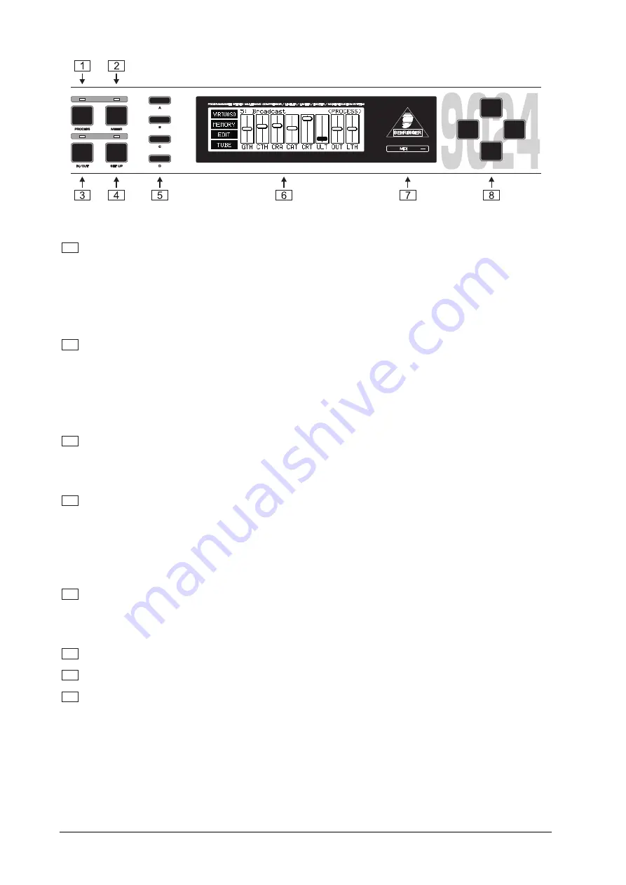
Fig. 1.2: The front panel controls
1
Press the
PROCESS
key to quickly and conveniently access all of the unit's major program functions
via virtual faders. This permits you to call up, save and edit programs with ease. The ULTRA-DYNE
PRO's factory presets are a solid foundation for a variety of applications. The automatic
VIRTUOSO and ULTRAMIZER functions permit the convenient customization of these applications to
suit your audio material. The first setup level provides global access to the parameters of all bands
simultaneously, while the second permits the manual adjustment of band-specific controls.
Here you will also find a screen for access to the Tube and Exciter functions.
2
Press the
METER
key for a multiple level display with the levels of the individual bands, as well as those
of the input and output signals. In addition, the respective level differences to the original signal are
also displayed.
+
The last fader used remains active when switching from the PROCESS to the METER operating
mode. The parameter in question may still be modified using the vertical cursor keys while
monitoring changes to the signal processing on the corresponding display.
3
Press the
IN/OUT
key to include the ULTRA-DYNE PRO in the signal path (green LED) or switch to
bypass mode (LED is dark). The LED flickering red indicates DSP overflow. This does not necessarily
mean clipping. Flickering starts as soon as an internal processing overflow occurs, while input and
output levels may be OK. When this LED lights up often, reduce the input level.
4
Press the
SETUP
key to access the setup levels which permit the individual numerical editing of each
parameter. Pressing the SETUP key briefly accesses the first setup level in which the complete range
of values for all available ULTRA-DYNE PRO parameters can be edited (see Chapter 2.1.4).
Holding the SETUP key for about two seconds switches to the second SETUP level. Here all the basic
settings of the device can be found, such as the choice of input source, sample rate, password
protection, MIDI configuration etc.
5
Four
SOFTKEYS
marked A, B, C and D are arranged vertically to the left of the display. The functions
of these keys are defined by the user software and are indicated by a pictogram or text to the right of
each key in the display. Each pictogram and its associated functions will be explained in detail in
Chapter 2.
6
Central in the control of the ULTRA-DYNE PRO is the LED-backlit 240 x 64
DI
SPLAY
.
7
The
MIDI LED
which displays the input of MIDI data is located to the right of the display.
8
The
CURSOR KEYS
are also positioned to the right of the display. These keys can be used for the
selection (horizontal) and operation (vertical) of the faders shown on the display, as well as the selection
of parameter fields in the SETUP menu.
+
In each case if you hold the key being used and then press the opposite key you will acceler-
ate whatever operation you are undertaking.
1. INTRODUCTION


