background image

Appendix

EL33xx-00x0

189

Version: 4.2

6.3.2

Firmware explanation

Determining the firmware version

Determining the version on laser inscription

Beckhoff EtherCAT slaves feature serial numbers applied by laser. The serial number has the following
structure: 

KK YY FF HH

KK - week of production (CW, calendar week)
YY - year of production
FF - firmware version
HH - hardware version

Example with ser. no.: 12 10 03 02:

12 - week of production 12
10 - year of production 2010
03 - firmware version 03
02 - hardware version 02

Determining the version via the System Manager

The TwinCAT System Manager shows the version of the controller firmware if the master can access the
slave online. Click on the E-Bus Terminal whose controller firmware you want to check (in the example
terminal 2 (EL3204)) and select the tab 

CoE Online

 (CAN over EtherCAT).

CoE Online and Offline CoE

Two CoE directories are available: 
• 

online

: This is offered in the EtherCAT slave by the controller, if the EtherCAT slave supports this.

This CoE directory can only be displayed if a slave is connected and operational.
• 

offline

: The EtherCAT Slave Information ESI/XML may contain the default content of the CoE.

This CoE directory can only be displayed if it is included in the ESI (e.g. "Beckhoff EL5xxx.xml").

The Advanced button must be used for switching between the two views.

In Fig. 

Display of EL3204 firmware version

 the firmware version of the selected EL3204 is shown as 03 in

CoE entry 0x100A.

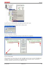
Fig. 199: Display of EL3204 firmware version

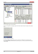
In (A) TwinCAT 2.11 shows that the Online CoE directory is currently displayed. If this is not the case, the
Online directory can be loaded via the 

Online

 option in Advanced Settings (B) and double-clicking on

AllObjects

.

Содержание EL33-00 Series

Страница 1: ...Documentation EL33xx 00x0 Analog thermocouple input terminal open circuit recognition 1 2 4 ch 4 2 2018 10 02 Version Date...

Страница 2: ......

Страница 3: ...26 2 4 2 Technical data 27 2 5 EL3318 28 2 5 1 Introduction 28 2 5 2 Technical data 29 2 6 TC technology basics 30 2 7 Use of EL33xx in the TwinCAT System Manager 31 2 8 Start 32 3 Basics communicati...

Страница 4: ...5 1 TwinCAT Quick Start 75 5 1 1 TwinCAT 2 77 5 1 2 TwinCAT 3 87 5 2 TwinCAT Development Environment 99 5 2 1 Installation of the TwinCAT real time driver 99 5 2 2 Notes regarding ESI device descript...

Страница 5: ...12 1 Full scale value FSV 170 5 12 2 Measuring error measurement deviation 170 5 12 3 Temperature coefficient tK ppm K 171 5 12 4 Single ended differential typification 172 5 12 5 Common mode voltage...

Страница 6: ...Table of contents EL33xx 00x0 6 Version 4 2...

Страница 7: ...l the requirements for safety including all the relevant laws regulations guidelines and standards Disclaimer The documentation has been prepared with care The products described are however constantl...

Страница 8: ...ht Beckhoff Automation GmbH Co KG Germany The reproduction distribution and utilization of this document as well as the communication of its contents to others without express authorization are prohib...

Страница 9: ...trained specialists in control automation and drive engineering who are familiar with the applicable national standards Description of instructions In this documentation the following instructions are...

Страница 10: ...14 0010 3 4 Update chapter Notes on the documentation Correction of Technical data Addenda chapter TwinCAT Quick Start Update revision status 3 3 Addenda chapter Operation with an external reference p...

Страница 11: ...notes 1 7 Addenda technical notes 1 6 Addenda technical notes 1 5 Addenda technical notes 1 4 Addenda Technical data and CoE objects 1 3 Connection diagrams corrected 1 2 Technical data added 1 1 Tech...

Страница 12: ...y Beckhoff In principle a device with a higher revision can replace a device with a lower revision unless specified otherwise e g in the documentation Associated and synonymous with each revision ther...

Страница 13: ...u hardware version of the I O PCB Example D 22081501 calendar week 22 of the year 2008 firmware version of bus PCB 1 hardware version of bus PCB 5 firmware version of I O PCB 0 no firmware necessary f...

Страница 14: ...14 Version 4 2 Fig 2 EK1100 EtherCAT coupler standard IP20 IO device with serial batch number Fig 3 CU2016 switch with serial batch number Fig 4 EL3202 0020 with serial batch number 26131006 and uniq...

Страница 15: ...ber 158102 Fig 6 EP1908 0002 IP67 EtherCAT Safety Box with batch number date code 071201FF and unique serial number 00346070 Fig 7 EL2904 IP20 safety terminal with batch number date code 50110302 and...

Страница 16: ...Product overview EL33xx 00x0 16 Version 4 2 2 Product overview 2 1 EL3311 EL3312 EL3314 2 1 1 Introduction Fig 9 EL3311...

Страница 17: ...Product overview EL33xx 00x0 17 Version 4 2 Fig 10 EL3312 Fig 11 EL3314...

Страница 18: ...Product overview EL33xx 00x0 18 Version 4 2 Fig 12 EL3314 0002 Fig 13 EL3314 0010...

Страница 19: ...temperature range is realized with the aid of a microprocessor The temperature range can be selected freely The error LEDs indicate a broken wire Compensation for the cold junction is made through an...

Страница 20: ...nd fil ter setting default approx 125 ms approx 2 5 s to 20 ms depending on configuration and fil ter setting default approx 250 ms Measuring error 0 3 relative to full scale value Voltage supply for...

Страница 21: ...e to cross currents Various types of thermocouple are supported the voltage is calculated in temperature directly in the terminal A broken wire is signalled by the error LEDs and on the fieldbus Cold...

Страница 22: ...270 1372 C default 1 8 C Typ L 50 900 C 1 8 C Typ N 270 1300 C 2 5 C Typ R 50 1768 C 4 0 C Typ S 50 1768 C 4 0 C Typ T 270 400 C 1 8 C Typ U 50 600 C 1 8 C Typ C 0 2329 C 3 5 C The given measuring er...

Страница 23: ...the pre scribed position 56 See note 56 Approval CE 2 3 EL3314 0010 2 3 1 Introduction Fig 16 EL3314 0010 High precision 4 channel analog input terminal for thermocouples with open circuit recognitio...

Страница 24: ...sured value external cold junction compensation reference junction compensation is possible since FW03 We advise against the use of compensation wires because they reduce the measuring accuracy of the...

Страница 25: ...768 C 4 0 C Typ T 270 400 C 1 8 C Typ U 50 600 C 1 8 C Typ C 0 2329 C 3 5 C The measuring error specified here is a result of several factors including the measuring error of the voltage measurement s...

Страница 26: ...ety tasks in any network or fieldbus The standard functions and features of the I Os remain available The data from these TwinSAFE SC I Os is fed to the TwinSAFE Logic where they undergo safety relate...

Страница 27: ...Conversion time approx 2 5 s up to 20 ms depending on configuration and filter setting default approx 250 ms Measuring error 0 3 relative to full scale value Power supply for electronics via the E bu...

Страница 28: ...technique A microprocessor handles linearization across the whole temperature range which is freely selectable The error LEDs indicate a broken wire Compensation for the cold junction is made through...

Страница 29: ...ing error 0 3 relative to full scale value Voltage supply for electronics via the E bus Distributed Clocks Current consumption via E bus typ 210 mA Bit width in the process data image max 32 byte inpu...

Страница 30: ...Thermocouples can be classified as active transducers They exploit the thermo electric effect Seebeck Peltier Thomson A voltage referred to as thermovoltage occurs over the length of a cable with diff...

Страница 31: ...verview of suitable thermocouples The following thermocouples are suitable for temperature measurement Type according to EN60584 1 Element Implemented temperature range Color coding sheath plus pole m...

Страница 32: ...t value undershot Error The error bit is set if the process data is invalid cable break over range under range TxPDO State Validity of the data of the associated TxPDO 0 valid 1 invalid TxPDO Toggle T...

Страница 33: ...Product overview EL33xx 00x0 33 Version 4 2 mount the EL33xx as described in the chapter Mounting and wiring 45 configure the EL33xx in TwinCAT as described in the chapter Commissioning 75...

Страница 34: ...IEC 8802 3 Pin Color of conductor Signal Description 1 yellow TD Transmission Data 2 orange TD Transmission Data 3 white RD Receiver Data 6 blue RD Receiver Data Due to automatic cable detection auto...

Страница 35: ...inal for longer than the set and activated SM watchdog time e g in the event of a line interruption the watchdog is triggered and the outputs are set to FALSE The OP state of the terminal is unaffecte...

Страница 36: ...If the checkbox is not activated nothing is downloaded and the ESC settings remain unchanged Multiplier Multiplier Both watchdogs receive their pulses from the local terminal cycle divided by the watc...

Страница 37: ...switching off of the SM watchdog via SM watchdog 0 is only implemented in terminals from version 0016 In previous versions this operating mode should not be used CAUTION Damage of devices and undefin...

Страница 38: ...erational Safe Op During transition between Pre Op and Safe Op the EtherCAT slave checks whether the sync manager channels for process data communication and if required the distributed clocks setting...

Страница 39: ...ibration values for analog measurement or passwords The order is specified in 2 levels via hexadecimal numbering main index followed by subindex The value ranges are Index 0x0000 0xFFFF 0 65535dez Sub...

Страница 40: ...meters are still available after a restart The situation may be different with other manufacturers An EEPROM is subject to a limited lifetime with respect to write operations From typically 100 000 wr...

Страница 41: ...e is to be stored permanently enter it in the Startup list The order of the Startup entries is usually irrelevant Fig 25 Startup list in the TwinCAT System Manager The Startup list may already contain...

Страница 42: ...ne The actual current slave list is read This may take several seconds depending on the size and cycle time The actual identity is displayed The firmware and hardware version of the equipment accordin...

Страница 43: ...he placeholder n tends to be used for the individual channel numbers In the CoE system 16 indices each with 255 subindices are generally sufficient for representing all channel parameters The channel...

Страница 44: ...it 1 ns Zero point 1 1 2000 00 00 Size 64 bit sufficient for the next 584 years however some EtherCAT slaves only offer 32 bit support i e the variable overflows after approx 4 2 seconds The EtherCAT...

Страница 45: ...AFE components comply with the current standards on electromagnetic compatibility with regard to spurious radiation and immunity to interference in particular However in cases where devices such as mo...

Страница 46: ...sulating materials synthetic fibers plastic film etc b Surroundings working place packaging and personnel should by grounded probably when handling with the devices c Each assembly must be terminated...

Страница 47: ...he lock clicks onto the mounting rail If the terminals are clipped onto the mounting rail first and then pushed together without tongue and groove the connection will not be operational When correctly...

Страница 48: ...onents The six spring contacts of the K Bus E Bus deal with the transfer of the data and the supply of the Bus Terminal electronics The power contacts deal with the supply for the field electronics an...

Страница 49: ...nts for testing these Power Feed Terminals can be released and pulled at least 10 mm from the group of terminals WARNING Risk of electric shock The PE power contact must not be used for other potentia...

Страница 50: ...elief and the wire connection should be kept as short as possible A distance of approx 10 cm should be maintained to the cable duct 4 8 Connection 4 8 1 Connection system WARNING Risk of electric shoc...

Страница 51: ...connection wires when the connector is removed Conductor cross sections between 0 08 mm2 and 2 5 mm2 can continue to be used with the proven spring force technology The overview and nomenclature of th...

Страница 52: ...n t toggle 2 The wire can now be inserted into the round terminal opening without any force 3 The terminal point closes automatically when the pressure is released holding the wire securely and perman...

Страница 53: ...m2 Wire size width fine wire conductors 0 25 1 5 mm2 Wire size width conductors with a wire end sleeve 0 14 0 75 mm2 Wire size width ultrasonically bonded conductors only 1 5 mm2 Wire stripping length...

Страница 54: ...re than 2 passive termi nals Examples for positioning of passive terminals highlighted Fig 36 Correct positioning Fig 37 Incorrect positioning 4 10 Installation positions 331x 0000 NOTE Constraints re...

Страница 55: ...ables optimum cooling of the electronics through convection From below is relative to the acceleration of gravity Fig 38 Recommended distances for standard installation position Compliance with the di...

Страница 56: ...other components above and below the terminal in order to guarantee adequate ventilation Prescribed installation position The prescribed installation position requires the mounting rail to be install...

Страница 57: ...ng EL33xx 00x0 57 Version 4 2 Fig 40 Recommended distances for standard installation position Compliance with the distances shown in Fig Recommended distances for standard installation position is str...

Страница 58: ...x communication and different standard settings set flashing slowly State of the EtherCAT State Machine SAFEOP verification of the sync manager channels and the distributed clocks Outputs remain in sa...

Страница 59: ...ication and different standard settings set flashing slowly State of the EtherCAT State Machine SAFEOP verification of the sync manager channels and the distributed clocks Outputs remain in safe state...

Страница 60: ...Mounting and wiring EL33xx 00x0 60 Version 4 2 4 12 3 EL3314 EL3314 00xx LEDs Fig 43 EL3314 Fig 44 EL3314 0002...

Страница 61: ...Mounting and wiring EL33xx 00x0 61 Version 4 2 Fig 45 EL3314 0010 Fig 46 EL3314 0090...

Страница 62: ...and different standard settings set flashing slowly State of the EtherCAT State Machine SAFEOP verification of the sync manager channels and the distributed clocks Outputs remain in safe state on Stat...

Страница 63: ...unication and different standard settings set flashing slowly State of the EtherCAT State Machine SAFEOP verification of the sync manager channels and the distributed clocks Outputs remain in safe sta...

Страница 64: ...e maximum permitted current on the signal relevant terminal points inputs GND is 40 mA if ap plicable EL3311 Connection Terminal point No Comment Input TC1 1 Input TC1 n c 2 not connected GND 3 Ground...

Страница 65: ...tted current on the signal relevant terminal points inputs GND is 40 mA if ap plicable EL3312 Connection Terminal point No Comment Input TC1 1 Input TC1 Input TC2 2 Input TC2 GND 3 Ground internally c...

Страница 66: ...Mounting and wiring EL33xx 00x0 66 Version 4 2 4 13 3 EL3314 00x0 Connection Fig 50 EL3314 Fig 51 EL3314 0002...

Страница 67: ...Mounting and wiring EL33xx 00x0 67 Version 4 2 Fig 52 EL3314 0010 Fig 53 EL3314 0090 Earthed thermocouples Observe for earthed thermocouples Differential inputs max 2 V to ground...

Страница 68: ...and wiring EL33xx 00x0 68 Version 4 2 EL3314 Connection Terminal point No Comment TC1 1 Input TC1 TC2 2 Input TC2 TC3 3 Input TC3 TC4 4 Input TC4 TC1 5 Input TC1 TC2 6 Input TC2 TC3 7 Input TC3 TC4 8...

Страница 69: ...nection Terminal point No Comment TC1 1 Input TC1 TC2 2 Input TC2 TC3 3 Input TC3 TC4 4 Input TC4 TC5 5 Input TC5 TC6 6 Input TC6 TC7 7 Input TC7 TC8 8 Input TC8 TC1 9 Input TC1 TC2 10 Input TC2 TC3 1...

Страница 70: ...hermocouple Do not connect GND to the shielding For EL3312 potential difference max 2 V Potential free earth free thermocouple GND can be connected to the shielding or GND can connected to any potenti...

Страница 71: ...rtification according to UL508 with limited power consumption The current consumed by the de vice is limited to a max possible current consumption of 4 A Devices with this kind of certification are ma...

Страница 72: ...against the rated operating voltage being exceeded by more than 40 due to short term interference voltages The individual terminals may only be unplugged or removed from the Bus Terminal system if the...

Страница 73: ...rotect against the rated operating voltage being exceeded by more than 40 due to short term interference voltages The individual terminals may only be unplugged or removed from the Bus Terminal system...

Страница 74: ...the Beckhoff terminal systems in potentially explosive ar eas ATEX Pay also attention to the continuative documentation Notes about operation of the Beckhoff terminal systems in potentially explosive...

Страница 75: ...anager I O Configuration In particular TwinCAT driver installation Fieldbus components Fieldbus Cards and Switches FC900x PCI Cards for Ethernet Installation Devices contain the terminals for the actu...

Страница 76: ...sed on the following sample configuration the subsequent subsections describe the procedure for TwinCAT 2 and TwinCAT 3 Control system PLC CX2040 including CX2100 0004 power supply unit Connected to t...

Страница 77: ...which case the EK1100 coupler wouldn t be necessary 5 1 1 TwinCAT 2 Startup TwinCAT basically uses two user interfaces the TwinCAT System Manager for communication with the electromechanical component...

Страница 78: ...t be made known first In the menu under Actions Choose Target System via the symbol or the F8 key open the following window Fig 59 Selection of the target system Use Search Ethernet to enter the targe...

Страница 79: ...t have to be set to Config mode via or via menu Actions Set Reset TwinCAT to Config Mode Shift F4 Fig 61 Select Scan Devices Confirm the warning message which follows and select EtherCAT in the dialog...

Страница 80: ...then reads the elements present in the configuration below Fig 64 Reading of individual terminals connected to a device This functionality is useful if the actual configuration is modified at short n...

Страница 81: ...hart Editor CFC Sequential Function Chart SFC The following section refers to Structured Text ST After starting TwinCAT PLC Control the following user interface is shown for an initial project Fig 65...

Страница 82: ...successful compilation TwinCAT PLC Control creates a tpy file in the directory in which the project was stored This file tpy contains variable assignments and is not known to the System Manager hence...

Страница 83: ...em Manager The two variables bEL1004_Ch4 and nEL2008_value can now be assigned to certain process objects of the I O configuration Assigning variables Open a window for selecting a suitable process ob...

Страница 84: ...ltaneously activate Continuous and All types Note that the Continuous checkbox was also activated This is designed to allocate the bits contained in the byte of the variable nEL2008_value sequentially...

Страница 85: ...context menu of a PDO can be executed in the other direction so that the respective PLC instance can then be selected Activation of the configuration The allocation of PDO to PLC variables has now es...

Страница 86: ...ink the PLC with the real time system via menu option Online Login the F11 key or by clicking on the symbol The control program can then be loaded for execution This results in the message No program...

Страница 87: ...vironment areas available together with Microsoft Visual Studio after startup the project folder explorer appears on the left in the general window area cf TwinCAT System Manager of TwinCAT 2 for comm...

Страница 88: ...3 user interface First create a new project via or under File New Project In the following dialog make the corresponding entries as required as shown in the diagram Fig 76 Create new TwinCAT project T...

Страница 89: ...lled on the respective PLC TwinCAT can be used in local mode and thereby the next step is Insert Device 90 If the intention is to address the TwinCAT runtime environment installed on a PLC as developm...

Страница 90: ...een entered it is available for selection as follows a password may have to be entered After confirmation with OK the target system can be accessed via the Visual Studio shell Adding devices In the pr...

Страница 91: ...o be acknowledged Based on the sample configuration 76 described at the beginning of this section the result is as follows Fig 82 Mapping of the configuration in VS shell of the TwinCAT3 environment T...

Страница 92: ...trol supports all languages described in IEC 61131 3 There are two text based languages and three graphical languages Text based languages Instruction List IL Structured Text ST Graphical languages Fu...

Страница 93: ...PLC_example as project name for example and select a corresponding directory Fig 85 Specifying the name and directory for the PLC programming environment The Main program which already exists by sele...

Страница 94: ...Commissioning EL33xx 00x0 94 Version 4 2 Fig 86 Initial Main program of the standard PLC project To continue sample variables and a sample program have now been created...

Страница 95: ...der followed by the compile process Fig 88 Start program compilation The following variables identified in the ST PLC program with AT are then available in under Assignments in the project folder expl...

Страница 96: ...tion tree Fig 90 Selecting PDO of type BOOL According to the default setting certain PDO objects are now available for selection In this sample the input of channel 4 of the EL1004 terminal is selecte...

Страница 97: ...inks can also be checked by selecting a Goto Link Variable from the context menu of a variable The object opposite in this case the PDO is automatically selected Fig 92 Application of a Goto Link vari...

Страница 98: ...t the bottom right of the VS shell development environment The PLC system can then be started as described below Starting the controller Select the menu option PLC Login or click on to link the PLC wi...

Страница 99: ...Automation Visual Studio Integration Choice of the programming language Supports object orientated extension of IEC 61131 3 Usage of C C as programming language for real time applications Connection t...

Страница 100: ...ces listed under Compatible devices can be assigned a driver via the Install button A driver should only be installed on compatible devices A Windows warning regarding the unsigned driver can be ignor...

Страница 101: ...ties of the EtherCAT device can be opened by double click on Device EtherCAT within the Solution Explorer under I O After the installation the driver appears activated in the Windows overview for the...

Страница 102: ...Commissioning EL33xx 00x0 102 Version 4 2 Fig 99 Exemplary correct driver setting for the Ethernet port Other possible settings have to be avoided...

Страница 103: ...Commissioning EL33xx 00x0 103 Version 4 2 Fig 100 Incorrect driver settings for the Ethernet port...

Страница 104: ...where an EL6601 or similar devices are used it is useful to specify a fixed IP address for this port via the Internet Protocol TCP IP driver setting and to disable DHCP In this way the delay associat...

Страница 105: ...was current at the time when the TwinCAT build was created For TwinCAT 2 11 TwinCAT 3 and higher the ESI directory can be updated from the System Manager if the programming PC is connected to the Int...

Страница 106: ...ision 1019 or for an older revision The ESI must then be requested from the manufacturer in this case Beckhoff b an ESI is present for the EL2521 0000 device but only in an older revision e g 1018 or...

Страница 107: ...deleted as follows close all System Manager windows restart TwinCAT in Config mode delete OnlineDescription0000 xml restart TwinCAT System Manager This file should not be visible after this procedure...

Страница 108: ...x 00x0 108 Version 4 2 Reasons may include Structure of the xml does not correspond to the associated xsd file check your schematics Contents cannot be translated into a device description contact the...

Страница 109: ...presence of the actual I O environment drives terminals EJ modules If the configuration is to be prepared in advance of the system configuration as a programming system e g on a laptop this is only po...

Страница 110: ...ration 120 can also be carried out for comparison 5 2 5 OFFLINE configuration creation Creating the EtherCAT device Create an EtherCAT device in an empty System Manager window Fig 110 Append EtherCAT...

Страница 111: ...ces can be appended by right clicking on a device in the configuration tree Fig 114 Appending EtherCAT devices left TwinCAT 2 right TwinCAT 3 The dialog for selecting a new device opens Only devices f...

Страница 112: ...vision can be displayed as Extended Information Fig 116 Display of device revision In many cases several device revisions were created for historic or functional reasons e g through technological adva...

Страница 113: ...on This also enables subsequent replacement of devices without changing the configuration different specifications are possible for drives Example If an EL2521 0025 1018 is specified in the configurat...

Страница 114: ...Commissioning EL33xx 00x0 114 Version 4 2 Fig 119 EtherCAT terminal in the TwinCAT tree left TwinCAT 2 right TwinCAT 3...

Страница 115: ...e online search is not available in RUN mode production operation Note the differentiation be tween TwinCAT programming system and TwinCAT target system The TwinCAT 2 icon or TwinCAT 3 icon within the...

Страница 116: ...The respective devices are lo cated in the stored ESI data and integrated in the configuration tree in the default state defined there Fig 124 Example default state NOTE Slave scanning in practice in...

Страница 117: ...configuration B tsm in order to check the built machine However if the series machine production department now doesn t use B tsm but instead carries out a scan to create the productive configuration...

Страница 118: ...itched to online state OPERATIONAL Fig 130 Config FreeRun query left TwinCAT 2 right TwinCAT 3 In Config FreeRun mode the System Manager display alternates between blue and red and the EtherCAT device...

Страница 119: ...evice is detected i e an EtherCAT slave for which no ESI XML description is available In this case the System Manager offers to read any ESI that may be stored in the device This case is described in...

Страница 120: ...figuration is then replaced by the revision found this can affect the supported process data and functions If a scan is initiated for an existing configuration the actual I O environment may match the...

Страница 121: ...based on the higher revision number Device selection based on revision compatibility The ESI description also defines the process image the communication type between master and slave device and the d...

Страница 122: ...CAT offers a function Change to Compatible Type for the exchange of a device whilst retaining the links in the task Fig 139 Dialog Change to Compatible Type left TwinCAT 2 right TwinCAT 3 This functio...

Страница 123: ...tabs are now available for configuring the terminal And yet the dimension of complexity of a subscriber determines which tabs are provided Thus as illustrated in the example above the terminal EL3751...

Страница 124: ...ing the start up phase Tick the control box to the left of the input field in order to modify the default value Previous Port Name and port of the EtherCAT device to which this device is connected If...

Страница 125: ...modifications include mask out a channel displaying additional cyclic information 16 bit display instead of 8 bit data size etc In so called intelligent EtherCAT devices the process data information...

Страница 126: ...of incorrect configuration the EtherCAT slave usu ally refuses to start and change to OP state The System Manager displays an invalid SM cfg log ger message This error message invalid SM IN cfg or inv...

Страница 127: ...sent to the mailbox Move Up This button moves the selected request up by one position in the list Move Down This button moves the selected request down by one position in the list New This button add...

Страница 128: ...x Index and sub index of the object Name Name of the object Flags RW The object can be read and data can be written to the object read write RO The object can be read but no data can be written to the...

Страница 129: ...can specify which objects are displayed in the list Fig 148 Dialog Advanced settings Online via SDO Information If this option button is selected the list of the objects included in the object list of...

Страница 130: ...te the fault display If an EtherCAT slave fails during change of state it sets an error flag Example An EtherCAT slave is in PREOP state pre operational The master now requests the SAFEOP state safe o...

Страница 131: ...DC Synchron Input based DC Synchron Advanced Settings Advanced settings for readjustment of the real time determinant TwinCAT clock Detailed information to Distributed Clocks are specified on http inf...

Страница 132: ...st The PDO configuration can be modified by double clicking on an entry Column Description Index PDO index Size Size of the PDO in bytes Name Name of the PDO If this PDO is assigned to a Sync Manager...

Страница 133: ...ling task for diagnosis that is accurate for the current cycle when in operation not during commissioning are discussed below Fig 151 Selection of the diagnostic information of an EtherCAT Slave In ge...

Страница 134: ...khoff EL3102 2 channel analogue input terminal is used here as it offers both the communication diagnosis typical of a slave and the functional diagnosis that is specific to a channel Structures are c...

Страница 135: ...bly have effects on the process data of other Slaves that are located in the same Syn cUnit In order for the higher level PLC task or cor responding control applications to be able to rely on correct...

Страница 136: ...d locally in the slave depends on the device EL terminals except the EL66xx are able to save in this way The user must manage the changes to the StartUp list Commissioning aid in the TwinCAT System Ma...

Страница 137: ...al operation After the operating power is switched on an EtherCAT Slave must go through the following statuses INIT PREOP SAFEOP OP to ensure sound operation The EtherCAT Master directs these statuses...

Страница 138: ...set as standard EtherCAT Master OP Slaves OP This setting applies equally to all Slaves Fig 155 Default behaviour of the System Manager In addition the target state of any particular Slave can be set...

Страница 139: ...lave Fig 157 PLC function blocks Note regarding E Bus current EL ES terminals are placed on the DIN rail at a coupler on the terminal strand A Bus Coupler can supply the EL terminals added to it with...

Страница 140: ...above a warning message E Bus Power of Terminal is output in the logger window when such a configuration is activated Fig 159 Warning message for exceeding E Bus current NOTE Caution Malfunction possi...

Страница 141: ...ontext of safety relevant applications Detailed examples for the correct application of the TwinSAFE SC components and the respective normative classification which were confirmed calculated by T V S...

Страница 142: ...TwinSAFE SC terminal Only suitable TwinSAFE SC terminals are offered in the selection dialog Fig 163 Creating a link to TwinSAFE SC terminal The CRC to be used can be selected or a free CRC can be en...

Страница 143: ...all available process data available The Safety Parameters tab typically contains no parameters The process data size and the process data themselves can be selected under the Process Image tab Fig 16...

Страница 144: ...so be set in the alias device as FSoE address under the Linking tab Under the object 0x80n0 02 Connection Mode the CRC to be used is selected or a free CRC is entered A total of 8 CRCs are available A...

Страница 145: ...12 Index Index of excluded PDOs Size byte bit Name PDO content 0x160n 2 0 TC Outputs Channel n Index 0x70n0 11 160 CJCompensation SM3 PDO Assignment 0x1C13 Index Index of excluded PDOs Size byte bit N...

Страница 146: ...rCAT devices as per ESI XML description the process data for input and output can be activated simultaneously through suitable predefined sets via Predefined PDO assignment The EL33xx devices have the...

Страница 147: ...TwinCAT System Manager with the predefined PDO selection External Compensation In the External Compensation option A or with ColdJunction Compensation EL3311 EL3312 EL3314 the input and output PDOs 0x...

Страница 148: ...I Module 1 Value INT 2 0 6010 11 AI Module 2 Value INT 2 0 6020 11 AI Module 2 Value INT 2 0 6030 11 AI Module 2 Value INT 2 0 The process data of all four channels are transmitted by default Via the...

Страница 149: ...on range for 16 bit 32768 32767 Example 1000 0000 0000 0000bin 0x8000hex 32768dec 1111 1111 1111 1110bin 0nFFFEhex 2dec 1111 1111 1111 1111bin 0nFFFFhex 1dec 0000 0000 0000 0001bin 0n0001hex 1dec 0000...

Страница 150: ...rsion time of the terminal It is parameterized via the indices 0x80n0 15 157 The higher the filter frequency the faster the conversion time Index 0x80n0 06 The filter function is always active even if...

Страница 151: ...Limit 2 Limit 1 and limit 2 index 0x80n0 13 157 index 0x80n0 14 157 not for EL3318 A temperature range can be set that is limited by the values in the indices 0x80n0 13 157 and 0x80n0 14 157 If the li...

Страница 152: ...ing gain The default value of 65536 dec corresponds to gain 1 The new gain value for 2 point user calibration after offset calibration is determined as follows Gain_new reference temperature measured...

Страница 153: ...80nF 01 AH Vendor calibration gain not changeable 0x80nF 02 BA User calibration offset can be activated via index 0x80n0 0A 0x80n0 17 AA User calibration gain can be activated via index 0x80n0 0A 0x80...

Страница 154: ...r and fieldbus as a variable external see fig External cold junction The reference data are written into index 0x70n0 11 160 Alternative to cold junction measurement As an alternative to the procedure...

Страница 155: ...CAT XML Device Description The display matches that of the CoE objects from the EtherCAT XML Device Description We rec ommend downloading the latest XML file from the download area of the Beckhoff web...

Страница 156: ...ters Index hex Name Meaning Data type Flags Default 1011 0 Restore default pa rameters 198 Restore default parameters UINT8 RO 0x01 1dec 1011 01 SubIndex 001 If this object is set to 0x64616F6C in the...

Страница 157: ...e limit 1 151 Limit 1 enabled BOOLEAN RW 0x00 0dec 80n0 082 3 Enable limit 2 151 Limit 2 enabled BOOLEAN RW 0x00 0dec 80n0 0A Enable user cali bration 152 Enabling of the user calibration BOOLEAN RW 0...

Страница 158: ...0 C to 2320 C 100 30 mV 1 V reso lution 101 60 mV 2 V reso lution 102 75 mV 4 V reso lution 0 Type K 270 C to 1372 C 1 Type J 210 C to 1200 C 2 Type L 50 C to 900 C 3 Type E 270 C to 1000 C 4 Type T 2...

Страница 159: ...hex Name Meaning Data type Flags Default 60n0 0 TC Inputs Maximum subindex UINT8 RO 0x11 17dec 60n0 01 Underrange Value below measuring range BOOLEAN RO 0x00 0dec 60n0 02 Overrange Measuring range ex...

Страница 160: ...RO 0x03 3dec 7040 01 TSC__Master Cmd reserved UINT8 RO 0x00 0dec 7040 02 TSC__Master ConnID reserved UINT16 RO 0x0000 0dec 7040 03 TSC__Master CRC_0 reserved UINT16 RO 0x0000 0dec 5 10 7 Information...

Страница 161: ...the EtherCAT slave STRING RO 00 Index 100A Software version Index hex Name Meaning Data type Flags Default 100A 0 Software version Firmware version of the EtherCAT slave STRING RO 01 Index 1018 Ident...

Страница 162: ...16 Index 1A0n TxPDO Map for Ch 1 8 0 n 7 Index hex Name Meaning Data type Flags Default 1A0n 0 TxPDO MapCh 1 PDO Mapping TxPDO 1 UINT8 RW 0x09 9dec 1A0n 01 SubIndex 001 1 PDO Mapping entry object 0x6...

Страница 163: ...C Inputs entry 0x11 Counter value INT16 RW 0x6030 11 16 1A04 09 SubIndex 009 9 PDO Mapping entry object 0x6040 TSC Slave Frame Elements entry 0x06 TSC__Slave CRC_3 UINT16 RW 0x6040 06 16 1A04 0A SubIn...

Страница 164: ...Minimum cycle time Minimum cycle time in ns UINT32 RO 0x00000000 0dec 1C32 06 Calc and copy time Minimum time between SYNC0 and SYNC1 event in ns DC mode only UINT32 RO 0x00000000 0dec 1C32 08 Comman...

Страница 165: ...SM 3 Event is supported no outputs available Bit 3 2 10 DC mode is supported Bit 5 4 10 input shift through local event outputs available Bit 5 4 101 input shift with SYNC1 event no outputs available...

Страница 166: ...undershot Error The error bit is set if the process data is invalid cable break overrange underrange TxPDO State Validity of the data of the associated TxPDO 0 valid 1 invalid TxPDO Toggle The TxPDO...

Страница 167: ...way Table 3 Status word Bit SW 15 SW 14 SW 13 SW 7 SW 6 SW 5 SW 4 SW 3 SW 2 SW 1 SW 0 Name TxPDO Toggle TxPDO State Error Limit 2 Limit 1 Overrange Underrange In addition to this the consolidated sta...

Страница 168: ...sentation under TwinCAT 2 11 Notes The consolidated representation is only visible from TwinCAT 2 11 and above For reasons of compatibility if a EL32xx xxxx 0017 or later is operated in earlier TwinCA...

Страница 169: ...s compatibility is permitted for the EL32xx xxxx 0016 and 0017 The easiest way to determine the revision that is installed in the terminal is through a scan of the EtherCAT system The comparison repor...

Страница 170: ...om Beckhoff the rule is that the limit with the largest value is chosen as the full scale value of the respective product also called the reference value and is given a positive sign This applies to b...

Страница 171: ...nd thermal stabiliza tion after a user calibration This applies to analog output devices 5 12 3 Temperature coefficient tK ppm K An electronic circuit is usually temperature dependent to a greater or...

Страница 172: ...a large R is used in order to ensure a high impedance For current measurements a small R is used as shunt If the purpose is resistance measurement corresponding considerations are applied Beckhoff gen...

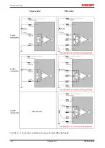
Страница 173: ...tential noiselessness voltage stability At this GND point a wire may be connected to make sure that VCM max is not exceeded in the differential sensor cable If differential channels are not electrical...

Страница 174: ...anufactured on the application side to be connected with the right polarity to Signal and Signal It is important to refer to the information page Configuration of 0 4 20 mA differential inputs see doc...

Страница 175: ...KL and related product groups exactly the same Differential EL3x1x 0 20 mA EL3x2x 4 20 mA KL and related product groups exactly the same Preferred current direction because of internal diode Preferred...

Страница 176: ...Commissioning EL33xx 00x0 176 Version 4 2 Single ended Differential Fig 184 2 3 and 4 wire connection at single ended and differential inputs...

Страница 177: ...under consideration For multi channel terminals boxes with resistive direct ohmic galvanic or capacitive connection between the channels the reference ground should preferably be the symmetry point of...

Страница 178: ...a user perspective they all have a common characteristic after the conversion a certain digital value is available in the controller for further processing This digital value the so called analog pro...

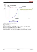
Страница 179: ...ronous or more quickly if the AI channel operates in slow FreeRun mode or more slowly e g with oversampling is then a question of the fieldbus setting and which modes the AI device supports For EtherC...

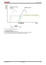
Страница 180: ...nerated externally with a frequency generator e g as sawtooth or sine A simultaneous square wave signal would be used as reference The signal delay ms s is then the interval between the applied electr...

Страница 181: ...9 Diagram signal delay linear 3 Additional information may be provided in the specification e g 3 1 Actual sampling rate of the ADC if different from the channel sampling rate 3 2 Time correction valu...

Страница 182: ...f example the terminal is continually switched between voltage and temperature measurement in the type K thus enabling a comparison of the two temperature values A recording of the measured values fro...

Страница 183: ...inear interpolation between the sampling points Fig 191 Structure of the sample program for separate temperature calculation with CJC in the PLC Download https infosys beckhoff com content 1033 el33xx...

Страница 184: ...rminate index of table nTabIndex TRUNC_INT nT_CJ nT_start nT_ResTab Calculate difference of two values with real value between them nDiff_U_node2node aTCElement nTabIndex 1 aTCElement nTabIndex Get re...

Страница 185: ...ll 3 parts with new data if the slave is set up for this purpose Generally the slave does not check whether the new data are suitable i e it may no longer be able to operate if the data are unsuitable...

Страница 186: ...revision 0016 The configured identifier must be compatible with the actual device description used as hardware i e the description which the slave has loaded on start up in this case EL3204 Normally...

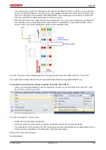
Страница 187: ...figuration is identical otherwise a change dialog appears for entering the actual data in the configuration Fig 196 Change dialog In this example in Fig Change dialog an EL3201 0000 0017 was found whi...

Страница 188: ...cted in the following dialog see Fig Selecting the new ESI The checkbox Show Hidden Devices also displays older normally hidden versions of a slave Fig 198 Selecting the new ESI A progress bar in the...

Страница 189: ...le terminal 2 EL3204 and select the tab CoE Online CAN over EtherCAT CoE Online and Offline CoE Two CoE directories are available online This is offered in the EtherCAT slave by the controller if the...

Страница 190: ...during a firmware update Switch to the Online tab to update the controller firmware of a slave see Fig Firmware Update Fig 200 Firmware Update Proceed as follows unless instructed otherwise by Beckhof...

Страница 191: ...update may be accomplished via an rbf file Controller firmware for processing I O signals FPGA firmware for EtherCAT communication only for terminals with FPGA The firmware version number included in...

Страница 192: ...ed right click the table header and select Properties in the context menu Fig 202 Context menu Properties The Advanced Settings dialog appears where the columns to be displayed can be selected Under D...

Страница 193: ...he terminal must have FPGA firmware version 10 or higher Older firmware versions can only be updated by the manufacturer Updating an EtherCAT device The following sequence order have to be met if no o...

Страница 194: ...Manager select the terminal for which the FPGA firmware is to be updated in the example Terminal 5 EL5001 and click the Advanced Settings button in the EtherCAT tab The Advanced Settings dialog appea...

Страница 195: ...to the device A download of firmware to an EtherCAT device must not be interrupted in any case If you interrupt this process by switching off power supply or disconnecting the Ethernet link the EtherC...

Страница 196: ...laced in BOOTSTRAP mode for a firmware update it does not check when downloading whether the new firmware is suitable This can result in damage to the device Therefore always make sure that the firmwa...

Страница 197: ...06 00 EL3314 0010 0016 2012 07 01 EL3314 0010 0017 2012 08 02 EL3314 0010 0018 2012 12 EL3314 0010 0019 2014 07 03 EL3314 0010 0020 2016 09 EL3314 0010 0021 2017 02 EL3314 0090 Hardware HW Firmware Re...

Страница 198: ...rs PDO Double click on SubIndex 001 to enter the Set Value dialog Enter the value 1684107116 in field Dec or the value 0x64616F6C in field Hex and confirm with OK Fig Entering a restore value in the S...

Страница 199: ...mponents there Beckhoff Headquarters Beckhoff Automation GmbH Co KG Huelshorstweg 20 33415 Verl Germany Phone 49 0 5246 963 0 Fax 49 0 5246 963 198 e mail info beckhoff com Beckhoff Support Support of...

Страница 200: ...Fig 11 EL3314 17 Fig 12 EL3314 0002 18 Fig 13 EL3314 0010 18 Fig 14 EL3314 0090 19 Fig 15 EL3314 0002 21 Fig 16 EL3314 0010 23 Fig 17 EL3314 0090 26 Fig 18 EL3318 28 Fig 19 Principle of the thermocou...

Страница 201: ...the TwinCAT PLC Control project 82 Fig 68 PLC project integrated in the PLC configuration of the System Manager 83 Fig 69 Creating the links between PLC variables and process objects 83 Fig 70 Select...

Страница 202: ...107 Fig 108 Using the ESI Updater TwinCAT 2 11 109 Fig 109 Using the ESI Updater TwinCAT 3 109 Fig 110 Append EtherCAT device left TwinCAT 2 right TwinCAT 3 110 Fig 111 Selecting the EtherCAT connecti...

Страница 203: ...Example of commissioning aid for a EL3204 137 Fig 155 Default behaviour of the System Manager 138 Fig 156 Default target state in the Slave 138 Fig 157 PLC function blocks 139 Fig 158 Illegally exceed...

Страница 204: ...gnal delay linear 181 Fig 190 Blue temperature values from the PLC calculation red PDO values in the temperature mea surement range 182 Fig 191 Structure of the sample program for separate temperature...

Отзывы: