Commissioning
CP39xx-14xx-0010
25
Version: 1.1
4.2
Mounting
The CP39xx-14xx-0010 stainless steel Control Panel is designed for installation on a mounting arm system.
Note the ambient conditions specified for operation (chapter 8
The Control Panel is installed on the mounting arm system using a mounting arm adapter. There are six M5
threaded holes at the back of the Control Panel for installation on the mounting arm system. In addition, the
mounting arm adapter is equipped with anti-twist protection, so that damage to the connection cable and the
Control Panel is prevented. The following ordering options are available, if you require a Beckhoff mounting
arm adapter for the installation.
Table 19: Mounting arm adapter ordering option
Order identifier
Execution
C9900-M759
Rotatable mounting arm adapter, stainless steel, 1.4404, brushed grain 240,
mounting arm installation from
above or below.
Single part, not mounted
A separate tube holder is required for mounting: C9900-M735 holder with
welded-on tube or C9900-M736 tube holder
Before you can attach the mounting arm adapter to the Control Panel, you must first prepare the C9900-
M735 mounting arm tube and place it in the desired position.
Table 20: Mounting arm tube ordering option
Order identifier
Execution
C9900-M735
Holder with welded-on 48 mm tube (length 150 cm, internal diameter
42 mm)
C9900-M736
Holder for 48 mm tube (must be welded)
For C9900-M759 CP3xxx-14xx mounting arm adapter, stainless steel
Mounting arm tube installation
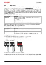
To ensure trouble-free installation of the tube, follow the steps shown in Fig. 16:
1. Apply the two red O-rings at the designated position on the tube.
2. Apply the PTFE paste supplied to the red marked area with a brush or spatula.
ð
The tube is now prepared.
A
A
A
B
Fig. 16: CP39xx-14xx-0010_mounting arm tube installation
Pay attention to the notes on the safety data sheet for the PTFE paste: Safety_data_sheet_mounting_paste-
PAO-PTFE-
Содержание CP39-14-0010 Series
Страница 2: ......
Страница 4: ...Table of contents CP39xx 14xx 0010 4 Version 1 1...
Страница 35: ...Commissioning CP39xx 14xx 0010 35 Version 1 1 Fig 35 CP39xx 1414 0010_circuit diagram...
Страница 53: ......

