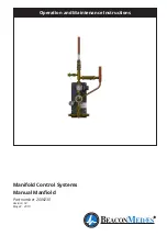
BeaconMedaes Manfiold Скачать руководство пользователя страница 10

10

Manual Manifold

2006230.03

Figure 6 - Typical cylinder header & extension 

layout details (See table 4 for part number 

references).

Note - If optional high pressure bank valves 

are installed, add typically 110mm per side 

for manifold assembly length

Figure 5 - Optional Cylinder Content Alarm Wiring

5

Cylinder content gauge

(Wired on site)

7

8

Cylinder content 

alarm input

(Wired on site)

6

1

3

4

2

3

2

7

6

2.3  Installation procedure for 

Modular Manifold Header - See 

figure 6


CAUTION: Ensure that all the header rails 

supplied are the correct gas type.  The gas ID is 

stamped onto the flat section of the NRV caps.

Note - All header runs start with a primary header unit 

with short stub pipe, secondary headers with longer 

stub pipes are used for any additional units.  See 

figure 6 for typical examples.

2.3.1   Fit the cylinder header to the mounting 

bracket with the M6 button head screws and washers 

supplied in kit.  Line up the first header to the mani

-

fold 5/8” connection point.

2.3.2  Ensure the bracket is level, mark the mounting 

hole positions and drill.  Fit the wall plugs and secure 

the header bracket with the No. 10 pan heads sup-

plied with the kit.


CAUTION: Supplied fixings are for use with 

solid masonry type walls only.  Typical cylinder 

header Including bracket is 1.5kg per side.

2.3.3 For additional cylinder headers remove the 3/8” 

BSP blanking plug and bonded seal from the end of 

the primary header block and fit 3/8” x 5/8” BSP fitting 

(supplied with kit) complete with O-ring seals for con-

nection of the next header.

2.3.4  Fit the next cylinder header to the mounting 

bracket with the M6 button head screws and wash-

ers supplied in the kit.  Offer the unit up to previous 

bracket and secure using the M6 x 16 hex head set 

screws and flange nut supplied with the extension 

kit.  Secure the header stub pipe to the previously 

fitted 5/8” connector.  

2.3.5  Mark the wall mounting points 

(see figure 

6)

, drill and secure in place.  Repeat previous steps 

until all headers have been fitted.

2.3.6  When all header extensions are installed, 

blank off the end of the most remote header 

with the 3/8” BSP plug and bonded seal that was 

removed in s

tep 2.3.3

.

3/8” x 5/8” header connector  

complete with o’ring seals

Gas specific non-

return valves

3/8” Plug and 

Bonded Seal

Cylinder 

Header

Mounting


Bracket

Note - 3/8” plug and bonded seal is required 

on the last cylinder header on each bank.

Wall mounting 

points

Cylinder 

securing 

chain D-link 

connection 

point

Cylinder chain pin hook points

Содержание Manfiold

Страница 1: ...Operation and Maintenance Instructions Manifold Control Systems Manual Manfiold Part number 2006230 Revision 03 May 24 2019...

Страница 2: ...Telephone 44 0 1246 474242 Email gbn info beaconmedaes com Website Contacts www beaconmedaes com BeaconMed s reserves the right to make changes and improvements to update products sold previously with...

Страница 3: ...Relief Valve Inspection 10 Cylinder Connection 6 Component Replace ment Procedures 11 Line Non return Valve Replacement 12 Test Sampling Point Valve Replace ment 13 2nd Stage Regulator Replacement 14...

Страница 4: ...ance must be fully trained in specialist work of this nature Oil grease and jointing compounds must not be used Do not attempt to prove the pressure relief valve under any circumstances by altering th...

Страница 5: ...ank valves 15 Single Line contact Module Not shown 16 Double Line contact Module Not shown 17 Manifold Headers C W NRVs 18 Tailpipes Notes Item 11 is recommended for indoor installations Item 15 16 ar...

Страница 6: ...ption Part Number Exhaust Pipe Connection Kit 2006233 Termination Box For Remote Alarm 2006219 4 Bar Pressure Switch with Line Contact Monitor 1829936 4 bar Pressure Switch without Line Contact Monito...

Страница 7: ...linder headers and tail pipes See table 4 for list of standard manifold assemblies Note tailpipes are supplied separate and may vary depending on required national standards enquire for details Additi...

Страница 8: ...and N2O O2 mix Entonox CAUTION Supplied fixings are for use with solid masonry type walls only Typical panel weight is 15kg selected fasteners are suitable for supporting the typical 15 kg weight of...

Страница 9: ...stall the first pipe support to the supplied 22mm OD stub pipe Item 10 figure 1 The next support fixture should typically be installed within 2m of the first 2 1 9 The 28mm exhaust line Optional suppl...

Страница 10: ...h the kit CAUTION Supplied fixings are for use with solid masonry type walls only Typical cylinder header Including bracket is 1 5kg per side 2 3 3 For additional cylinder headers remove the 3 8 BSP b...

Страница 11: ...11 Manual Manifold 2006230 03 Note For additional cylinders beyond 6 continue to add the above for either single or double racks...

Страница 12: ...inders on medical gas manifolds or medical equipment 2 4 3 Install the cylinder chains to the header brackets using the D link where shown on figure 6 Loop the chain around the cylinder to secure in p...

Страница 13: ...overall system is operable and set to the correct distribution pipeline pressure Suitably qualified competent personnel who are familiar with this manual must only undertake commissioning of the pane...

Страница 14: ...ves on the empty bank The empty cylinders must then be replaced See section 4 5 for cylinder handling and section 4 6 for cylinder operation 4 2 4 These steps must be repeated for continuous supply 4...

Страница 15: ...nts and when most explosions will occur due to adiabatic compression of any oil or grease that may be present 4 6 1 The cylinder valve should be FULLY opened slowly anticlockwise using the appropriate...

Страница 16: ...haust connections are flat face unions complete with o ring seals for ease of removal Figure 9 Relief Valve Maintenance Image shown with optional exhaust 5 3 5 Check the line pressure regulator set po...

Страница 17: ...eplace tailpipes pressure safety valve pressure regulator high pressure isolation valve isolation valves contact gauges non return valve etc as and when required see section 6 0 CAUTION For emergency...

Страница 18: ...part numbers Table 6 2nd Stage Regulator Part Numbers Regulator Nominal Pressure Part Number 4 Bar 2005689 7 Bar 2005690 6 4 1 Complete steps in section 6 1 before carrying out any component replacem...

Страница 19: ...ct the 1 connection the 5 8 header connection and the bracket M6 flange nuts as shown in figure 14 and gently remove the unit by sliding it towards you Take care not to damage the seals 6 5 4 Remove t...

Страница 20: ...raining the pipe work as shown in figure 16 Pipe line clamps may need to be unfastened to achieve this Figure 15 2nd Stage Relief Valve Replacement 2 x 1 flat face connections O ring P N 2000152 2nd S...

Страница 21: ...le 10 for part numbers Table 10 Line Pressure Gauge Part Numbers Nominal Line Pressure Part Number 4 Bar 2005765 7 Bar 2005766 CAUTION Ensure the new gauge has the same scale as the one being replaced...

Страница 22: ...ndustrial regulators are recommended to be replaced every 5 years Although the medical standards do not specifically identify the need to replace the regulators within this time scale it is considered...

Страница 23: ...CSA 2 4 4 8 10 2000179 O Ring 17 1 I D x 1 6 CSA 2 4 4 8 11 2000152 O Ring 22 1 I D x 1 6 CSA 2 4 4 8 12 2004808 1 4 Bonded Seal 2 4 4 8 13 1824977 3 8 Bonded Seal 2 4 4 8 14 1825637 1 2 Bonded Seal...

Страница 24: ...Copco Ltd trading as Atlas Copco Medical Unit 18 Nuffield Way Abingdon Oxfordshire UK OX14 1RL Tel 44 0 1246 474242 www beaconmedaes com 0088 Atlas Copco Airpower n v Boomsesteenweg 957 2610 Wilrijk B...

Отзывы: