If it becomes necessary to clean the heat exchangers because of
carbon deposits, soot, etc., proceed as follows.
NOTE:
Deposits of soot and carbon indicate a problem exists that
needs to be corrected. Action must be taken to correct the problem.
1. Turn off gas and electrical supplies to furnace.
2. Disconnect gas supply at ground joint union using a backup
wrench. Remove gas pipe from gas valve.
3. Disconnect electrical wiring from gas valve.
4. Remove burner/manifold assembly.
a. Remove manifold cover plate and air inlet plate/burner
removal cover.
b. Remove manifold retention plate from front of unit.
c. Loosen screws in manifold retention plate at rear of unit.
d. Disconnect ignition wire at pilot.
e. Remove burner/manifold assembly from unit.
5. Place burner/manifold assembly on flat work surface and
clean burner ports. Use a soft brush to loosen dirt, then
vacuum.
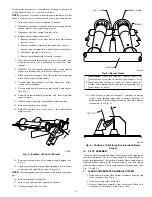
6. GENTLY tap each burner opening with a small, rubber
mallet to loosen any debris in heat exchanger cells.
7. Brush each heat exchanger cell with a nylon heat exchanger
brush with a long, flexible handle.
8. Vacuum each heat exchanger cell and burner box with a
crevice tool attachment.
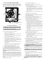
9. Check position and alignment of ignitor and flame sensor.
(See Fig. 5.)
10. Reinstall burner/manifold assembly and front manifold
retention plate.
11. Tighten screws securing rear manifold retention plate.
12. Reconnect ignition wire at pilot.
13. Reinstall manifold cover plate and air inlet plate/burner
removal cover.
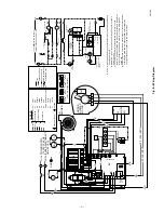
14. Reconnect wiring to gas valve using wiring diagram. (See
Fig. 8.)
15. Apply joint compound (pipe dope) sparingly to male ends
of gas pipe and reinstall gas pipe in gas valve.
NOTE:
Joint compound must be resistant to the action of propane
gas.
16. Reconnect ground joint union.
17. Turn on gas and electrical supplies to furnace.
18. Check gas supply line for leaks.
WARNING:
Never use matches, candles, flame, or
other sources of ignition to check for gas leakage. Use a
soap-and-water solution to check for leaks. Failure to
follow this warning could result in fire, explosion, per-
sonal injury, or death.
19. Check furnace operation through 2 complete operating
cycles. Look through sight-glass in burner enclosure to
check burners. Burner flames should be clear blue, almost
transparent. (See Fig. 4.)
IV.
PILOT ASSEMBLY
Check the pilot assembly and clean if necessary at the beginning of
each heating season. The pilot flame should be high enough for
proper impingement of the ignition electrode/flame sensor and to
light the burners. Remove any accumulation of soot and carbon
from the flame sensor. Check spark ignition electrode gap. (See
Fig. 3, 4, and 5.)
V.
CLEAN CONDENSATE DRAINAGE SYSTEM
1. Disconnect drain tube from bottom of inducer housing and
from vent pipe. (See Fig. 6.)
2. Disconnect condensate drain line.
3. Remove drain/hose assembly from furnace and flush with
water until clean. Ensure drain trap is clean.
Fig. 3—Position of Pilot to Burners
A91347
1
/
8
″
Fig. 4—Burner Flame
A84076
BURNER FLAME
PILOT FLAME
BURNER
MANIFOLD
Fig. 5—Position of Pilot to Ignition Electrode/Flame
Sensor
A91348
3
/
8
″
TO
1
/
2
″
—3—


