4. Flush external condensate drain line with water until clean.
5. Reassemble condensate drainage system.
VI.
ELECTRICAL CONTROLS AND WIRING
NOTE:
There may be more than 1 electrical supply to the unit.
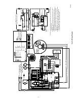
Refer to Fig. 7 for filed application wiring and Fig. 8 for unit
wiring. With power disconnected to the unit, check all electrical
connections for tightness. Tighten all screws on electrical connec-
tions. If any smokey or burned connections are found, disassemble
the connection, clean all parts, strip wire, and reassemble properly
and securely.
Reconnect electrical power to the unit and observe unit through 1
complete operating cycle. Electrical controls are difficult to check
without proper instrumentation. A good voltmeter is needed to
check for correct operation of controls and wiring.
If the furnace fails to operate, check the following items before
calling for service:
1. Is thermostat set correctly to "call for heat?"
2. Are electrical and gas supplies on?
3. Are filters clean?
VII.
WINTERIZING
The unit must not be installed, operated, and then turned off and
left off in an unoccupied structure during cold weather when the
temperature drops to 32°F and below. Freezing condensate left in
the furnace will damage the equipment.
If the furnace will be off for an extended period of time in a
structure where the temperature will drop to 32°F or below,
winterize as follows.
1. Mix a solution of equal amounts of ethylene glycol (Pre-
stone II antifreeze/coolant or equivalent) and water.
2. Turn off electrical supply to furnace.
3. Disconnect drain tube from bottom of inducer assembly.
4. Insert funnel in drain tube and pour antifreeze/water solu-
tion into furnace until it is visible at point where condensate
enters open drain.
5. Reconnect drain tube to inducer assembly.
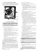
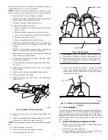
Fig. 6—Condensate Drainage System
A91176
1
″
INDUCER
HOUSING
TUBE
VENT DRAIN
TUBE
TO VENT
TERMINATION
Connect to approved
sewer system per these
instructions and local
codes.
NOTE:
Fig. 7—Heating and Cooling Application Wiring Diagram
A91338
1. Connect Y-terminal as shown for proper cooling operation.
2. If any of the original wire, as supplied, must be replaced,
use same type or equivalent wire.
3. Proper polarity must be maintained for 115-volt wiring.
NOTE :
115-VOLT
FIELD-SUPPLIED
FUSED DISCONNECT
24-VOLT
TERMINAL
BLOCK
TWO-WIRE
HEATING-
ONLY
FOUR
WIRE
THERMOSTAT
TERMINALS
FIELD-SUPPLIED
FUSED DISCONNECT
CONDENSING
UNIT
TWO
WIRE
W
Y
C
G
W
Y
R
GND
GND
FIELD 24-VOLT WIRING
FIELD 115-, 208/230-, 460-VOLT WIRING
FACTORY 24-VOLT WIRING
FACTORY 115-, 208/230-, 460-VOLT WIRING
208/230- OR
460-VOLT
THREE
PHASE
208/230-
VOLT
SINGLE
PHASE
G
R
GND
GND
GND
115-VOLT
SINGLE
PHASE
GND
—4—


