I.
AIR FILTER CLEANING AND REPLACEMENT
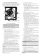
The air filter arrangement may vary depending on the application.
Each furnace is supplied with a permanent, washable filter and
wire filter retainer. The filter is normally located in the return-air
plenum opening in front of the blower. (See Fig. 2.)
CAUTION:
Never operate unit without a filter or with
filter access door removed. Failure to follow this warning
could result in a fire or personal injury.
To clean or replace the filters, proceed as follows.
1. Turn off electrical supply to unit.
2. Remove blower access door located at inlet (return-air) end
of furnace by removing 4 screws.
3. Bend wire filter retainer until it clears furnace flange and
swing retainer toward the blower.
4. Remove filter from furnace. Replace if filter is torn.
5. Clean permanent, washable filters by spraying cold tap
water through filter in opposite direction of airflow. A mild
liquid detergent may be used if necessary.
6. Rinse filters and let dry. Oiling or coating of filters is not
recommended.
7. Reinstall filters with cross-mesh binding facing blower.
8. Replace blower access door and reinstall 4 screws.
9. Turn ON electrical supply to furnace.
II.
BLOWER MOTOR AND WHEEL MAINTENANCE
For long life, economy, and high efficiency, clean accumulated dirt
and grease from blower wheel and motor annually.
The following items should be performed by a qualified service
technician.
Some motors have prelubricated, sealed bearings and require no
lubrication. These motors can be identified by the absence of oil
ports on each end of the motor. For motors with oil ports, lubricate
motor every 5 years if motor is used for intermittent operation
(thermostat FAN switch in AUTO position), or every 2 years if
motor is in continuous operation (thermostat FAN switch in ON
position).
Clean and lubricate as follows.
1. Turn off electrical supply to unit.
2. Remove blower access door by removing 4 screws.
3. Remove blower assembly.
a. Remove 4 screws securing front blower support bracket
and remove bracket. (See Fig. 2.)
b. Reach through 4-in. diameter holes in rear blower
support bracket and remove 2 screws securing bracket to
blower shelf using a 3/8-in. ratchet with a 3-in. exten-
sion. (See Fig. 2.)
c. Disconnect motor leads from motor speed selector. (See
Fig. 2.)
d. Remove blower assembly from unit.
4. Mark blower wheel location on shaft before disassembly to
ensure proper reassembly.
5. Loosen setscrew holding blower wheel on motor shaft.
6. Disconnect ground wire from blower housing.
7. Remove bolts holding motor mount to blower housing and
slide motor and mount out of housing.
8. Lubricate motor (when oil ports are provided).
a. Remove dust caps or plugs from oil ports located at each
end of motor. If motor does not have these caps or plugs,
bearings are sealed and need no further lubrication.
b. Use a good grade of SAE 20 nondetergent motor oil and
add 1 teaspoon (5 cc, 3/16 oz, or 16 to 25 drops) in each
oil port. The use of other types or grades of oil will
damage the motor. Excessive oiling can cause premature
bearing failures.
c. Allow time for total quantity of oil to be absorbed by
each bearing.
d. After oiling motor, wipe excess oil from motor housing.
e. Replace dust caps or plugs on oil ports.
9. Remove blower wheel from housing.
a. Mark blower wheel orientation and cutoff plate location
to ensure proper reassembly.
b. Remove screws securing cutoff plate and remove cutoff
plate from housing.
c. Remove blower wheel from housing.
10. Clean blower wheel and motor using a vacuum with soft
brush attachment. Be careful not to disturb balance weights
(clips) on blower wheel vanes. Do not drop or bend wheel
as balance will be affected.
11. Reassemble blower by reversing items 9.a. through 9.c.
Ensure wheel is positioned for proper rotation.
12. Reassemble motor and blower by reversing items 3 through
7. Reconnect motor ground wire.
CAUTION:
Ensure the motor is properly positioned in
the blower housing. The motor oil ports must be at a
minimum of 30° above the horizontal centerline of the
motor after the blower assembly has been reinstalled in
the furnace.
13. Reinstall blower assembly in furnace.
14. Connect electrical leads to motor speed selector. DO NOT
force leads.
15. Turn on electrical supply and check for proper rotation and
speed changes between heating and cooling.
III.
CLEANING HEAT EXCHANGERS AND BURNERS
The following items should be performed by a qualified service
technician.
Fig. 2—Blower Compartment
A91175
SCREWS (2)
BLOWER SUPPORT
BRACKET
FILTER
AIR
FLOW
SPEED
SELECTOR
—2—


