background image

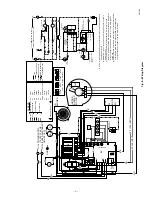
Fig.

8—Wiring

Diagram

A91349

H

M

L

C

INDOOR

BLOWER

MOTOR

BR

BR

CAP

.

I.D.

BLOWER

LEGEND

L1(H)

L2(N)

CIRCULATION

FAN

LOW

TSTAT

24VAC

(115 VAC)

NOTES:

(1) Make field power supply connections to black and white wires capped 

with orange wire nuts.

(2) WARNING --- Unit must be grounded. Wiring must conform to N.E.C. 

and local codes.

(3) If any of the original wire, as supplied with the furnace, must be 

replaced, it must be replaced with wiring material having a temperature 

rating of at least 185 C and be a minimum of 16 GA. AWG copper 

strand wire.

(4) Connect required motor lead to heat terminal on circuit board to deliver 

a temperature rise within the range specified on the rating plate.  

Connect unused motor leads to the "M1 & M2" terminals.

LINE Y 

24 V

PRINTED CIRCUIT

BOARD WIRING

FACTORY WIRING

FIELD WIRING

ORANGE WIRE NUT

GROUND

BK

BL

BR

GR

OR

RD

RD/BK

VI

WH

YL

BLACK

BLUE

BROWN

GREEN

ORANGE

RED

RED/BLACK STRIPE

VIOLET

WHITE

YELLOW

L

P

ROS

BI

CU

LIMIT

PRESSURE SWITCH

ROLL OUT SWITCH

BLOWER INTERLOCK

CONDENSING UNIT

115 VAC 1 0 60 HZ POWER SUPPLY

(FUSED DISCONNECT ON HOT LEG)

1

2

3

4

60 SEC

90 SEC

120 SEC

DELAY  OFF  SCREW SETTINGS

150 SEC 

MED

HI

GND

N2

HEAT

COOL

N3

D1

N4

C

BI

S1

S2

M2

K1

K2

K2

K3

X

R

Y

C

W

G

CN23-2

CN23-1

CN23-6

LIMIT

CONTROL

TRANSFORMER

CONDENSING

UNIT

PRESSURE SW.

N.O.

N.C.

PS1

PS2

V1

CN23-3

CN23-5

COM.

ST912081005

ELECTRONIC

FAN TIMER

ROS

MV

PV

MV\PV

MV

MV\PV

PV

24V (GNO)

GNO (BURNER)

SPARK

GAS VALVE

HONEYWELL VR8204

PILOT

24V

IGNITION MODULE

HONEYWELL S8600

OR 8660

N1

GNO

MV/PV

MV

G.V.

GND

PV

L1 (H)

L2 (N)

POWER SUPPLY

115 VAC 10 60 HZ

(FUSED DISCONNECT

ON HOT LEG)

GND

VI

ROS

P

BK

BK

CU

T

R

Y

W

G

BI

BK

WH

G

H

C

O

Y

R

L

RD

OR

VI

WH

RD

BK

GR

BK

YL

BL

VI

OR

PILOT

HONEYWELL

S8600

IS

1

2

3

4

5

6

7

8

9

MV

MV/PV

PV

GNO (BURNER)

24V (GNO)

24V

TH-W (OPT)

SPARK

WH

BL

RD/

BK

YL

BC

DELAY OFF

SELECT

A

B

H

E

A

T

C

O

O

L

M1

M2

M3

UNUSED

MOTOR

LEADS

S

1

2

3

4

5

6

1

2

3

4

D1

C

C

X

X

Y

100, 125K INPUT

50, 75K INPUT

BL

YL

INDUCER MOTOR

100,125

FOR 75, 100, 125

50, 75

—5—

Содержание Bryant Day&Night Payne A Series

Страница 1: ...ap powders bleaches waxes or other cleaning compounds plastic or plastic containers gasoline kerosene cigarette lighter fluid dry cleaning fluids or other volatile fluids 3 Paint thinners and other painting compounds paper bags or other paper products Failure to follow this warning can cause corrosion of the heat exchanger fire personal injury or death WARNING The ability to properly perform maint...

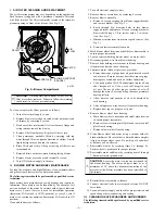
Страница 2: ...g a 3 8 in ratchet with a 3 in exten sion See Fig 2 c Disconnect motor leads from motor speed selector See Fig 2 d Remove blower assembly from unit 4 Mark blower wheel location on shaft before disassembly to ensure proper reassembly 5 Loosen setscrew holding blower wheel on motor shaft 6 Disconnect ground wire from blower housing 7 Remove bolts holding motor mount to blower housing and slide motor...

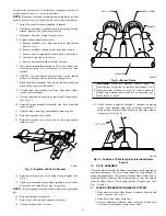
Страница 3: ...air inlet plate burner removal cover 14 Reconnect wiring to gas valve using wiring diagram See Fig 8 15 Apply joint compound pipe dope sparingly to male ends of gas pipe and reinstall gas pipe in gas valve NOTE Joint compound must be resistant to the action of propane gas 16 Reconnect ground joint union 17 Turn on gas and electrical supplies to furnace 18 Check gas supply line for leaks WARNING Ne...

Страница 4: ... equipment If the furnace will be off for an extended period of time in a structure where the temperature will drop to 32 F or below winterize as follows 1 Mix a solution of equal amounts of ethylene glycol Pre stone II antifreeze coolant or equivalent and water 2 Turn off electrical supply to furnace 3 Disconnect drain tube from bottom of inducer assembly 4 Insert funnel in drain tube and pour an...

Страница 5: ...RED RED BLACK STRIPE VIOLET WHITE YELLOW L P ROS BI CU LIMIT PRESSURE SWITCH ROLL OUT SWITCH BLOWER INTERLOCK CONDENSING UNIT 115 VAC 1 0 60 HZ POWER SUPPLY FUSED DISCONNECT ON HOT LEG 1 2 3 4 60 SEC 90 SEC 120 SEC DELAY OFF SCREW SETTINGS 150 SEC MED HI GND N2 HEAT COOL N3 D1 N4 C BI S1 S2 M2 K1 K2 K2 K3 X R Y C W G CN23 2 CN23 1 CN23 6 LIMIT CONTROL TRANSFORMER CONDENSING UNIT PRESSURE SW N O N ...

Страница 6: ... 1994 BDP Co P O Box 70 Indianapolis IN 46206 Printed in U S A 6 45002b Catalog No BDP 3334 920 ...

Отзывы: