2701
10
GB
ATTENTION
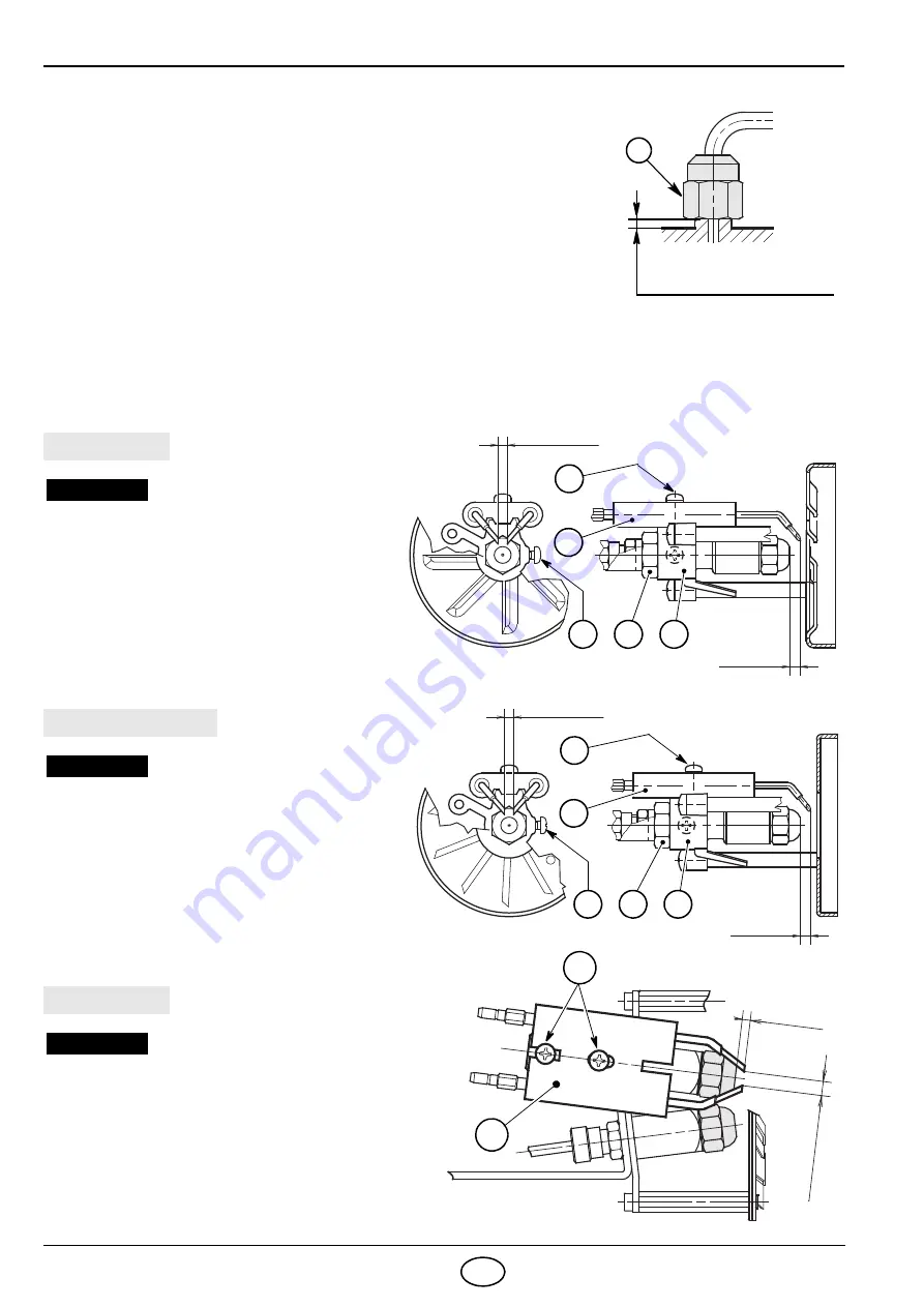
During the reassembly of the nozzle-holder assembly screw the nut (3) as
shown in the figure 14.
4.4
COMBUSTION HEAD SETTING,
(see fig. 12 or 13)
It depends on the output of the burner and is carried out by rotating clockwise
or counterclockwise the setting screw (6) until the set-point marked on the reg-
ulating rod (7) is level with the outside plane of the nozzle-holder assembly
(1). In the sketch, for burner CRONO 25-L2, the combustion head is set for an
output of 2,00 + 2,00 GPH at 12 bar. The set-point set-point
3
of the regulat-
ing rod (7) is at the same level with the outside plane of the nozzle-holder as-
sembly as shown in the schedule.
4.5 ELECTRODES ADJUSTMENT
3
TIGHTEN WITHOUT MOVING
BACKWARDS TO THE END
D5684
Fig. 14
TO HAVE ACCESS TO THE ELECTRODES CARRY OUT OPERATION AS DESCRIBED AT PAGE 9.
MEASURES MUST BE RESPECTED
Lean the diffuser disc-holder assembly (1) on
the nozzle-holder (2) and lock it by screw (3).
For prospective adjustments loosen screw (4)
and move the electrodes assembly (5).
WARNING
D5342
4 ÷ 5
mm
4.5
– 0.5 mm
0
4
5
1
2
3
CRONO 10-L2
D5341
6 ÷ 7
mm
4.5
– 0.5 mm
0
4
5
1
2
3
MEASURES MUST BE RESPECTED
Lean the diffuser disc-holder assembly (1) on
the nozzle-holder (2) and lock it by screw (3).
For prospective adjustments loosen screw (4)
and move the electrodes assembly (5).
WARNING
CRONO 15-L2, 20-L2
1
3
mm
4
.5
–
0
.5
m
m
0
D5406
2
MEASURES MUST BE RESPECTED
For prospective adjustments loosen screws (1)
and move the electrodes assembly (2).
WARNING
CRONO 25-L2
Fig. 16
Fig. 16
Fig. 16
Содержание CRONO 10-L2
Страница 16: ......
Страница 30: ......
Страница 44: ...R 6911 10 1212 CE Baxi Calefacción S L U 2012 ...


