2701
5
GB
4
3.3 HYDRAULIC SYSTEMS
WARNING:
O
It is necessary to install a filter on the fuel supply line.
O
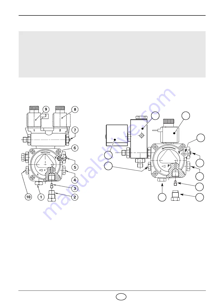
The pump is designed to allow working with two pipes. In order to obtain one pipe working it
is necessary to unscrew the return plug (2), remove the by-pass screw (3) and then screw
again the plug (2), (see fig. 7).
O
Before starting the burner make sure that the return pipe-line is not clogged. An excessive
back pressure would cause the damage of the pump seal.
D5405
5
4
2
3
6
9
7
10
8
1
1
- Suction line
2
- Return line
3
- By-pass screw
4
- Gauge connection
5
- 2nd stage pressure adjuster
6
- Suction gauge connection
7
- 1st stage pressure adjuster
8
- 2nd stage valve
9
- 1st stage valve
10
- Auxiliary pressure test point
1
- Suction line
2
- Return line
3
- By-pass screw
4
- Gauge connection
5
- 2nd stage pressure adjuster
6
- Suction gauge connection
7
- 1st stage valve
8
- Valve casing assembly
9
- 2nd stage valve
10
- Auxiliary pressure test point
CRONO 10-L2, 15-L2 and 20-L2
CRONO 25-L2
Fig. 7
Fig. 7
S7688
Содержание CRONO 10-L2
Страница 16: ......
Страница 30: ......
Страница 44: ...R 6911 10 1212 CE Baxi Calefacción S L U 2012 ...


