


clarity. The number associated with the winding (Dy1) can be almost any hour of the clock, hence the
term “around the clock” phase shifting.
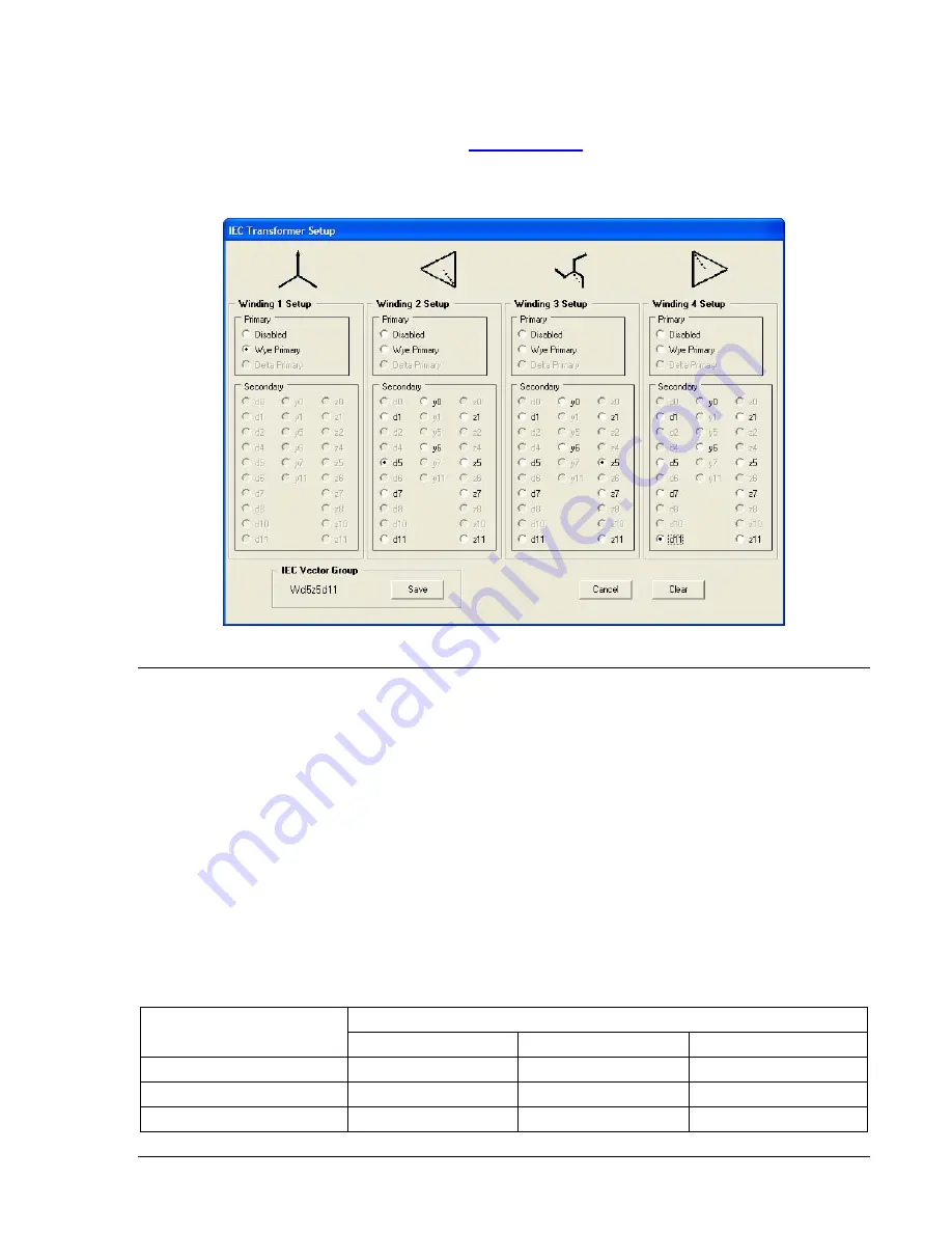
In transformer standards such as IEEE C57.12.00 and IEC-60076-1, there will be many variations on the
nomenclature and figures used to show how the phases are identified in a three-phase system. For
details on IEC transformer connections, go to
and download the technical paper titled
Three Phase Transformer Winding Configurations and Differential Relay Compensation
, which was
presented at the 2004 Western Protective Relay Conference.
Figure 3-7. IEC Transformer Setup Screen
CONTACT SENSING INPUTS
BE1-CDS240 relays have eight or twelve contact sensing inputs depending on style number to initiate
BE1-CDS240 relay actions. These inputs are isolated and require an external wetting voltage. Nominal
voltage(s) of the external dc source(s) must fall within the relay dc power supply input voltage range. To
enhance user flexibility, the BE1-CDS240 relay uses wide range AC/DC power supplies that cover
several common control voltage ratings. To further enhance flexibility, the input circuits are designed to
respond to voltages at the lower end of the control voltage range while not overheating at the high end of
the control voltage range.
Energizing levels for the contact sensing inputs are jumper selectable for a minimum of approximately 5
Vdc for 24 Vdc nominal sensing voltages, 26 Vdc for 48 Vdc nominal sensing voltages, or 69 Vdc for 125
Vdc nominal sensing voltages. See Table 3-7 for the control voltage ranges.
Each BE1-CDS240 is delivered with the contact-sensing jumpers installed for operation in the high end of
the control voltage range in “H” or high position. If the contact sensing inputs are to be operated at the
lower end of the control voltage range, the jumpers must be changed to the “L” or low position or
completely removed. See Section 12,
Installation,
for details on how to set the jumper positions in the
contact sensing input circuits.
Table 3-7. Contact Sensing Turn-On Voltage
Contact Sensing Turn-On Voltage
Nominal Control Voltage
Jumper (L) Position
Jumper (H) Position
Jumper Not Installed
24 Vdc
N/A
N/A
Approx. 5 Vdc
48/125 Vac/dc
26 to 38 Vac/dc
69 to 100 Vac/dc
N/A
125/250 Vac/dc
69 to 100 Vac/dc
138 to 200 Vac/dc
N/A
9365200990 Rev F
BE1-CDS240 Input and Output Functions
3-15
Содержание BE1-CDS240
Страница 1: ...INSTRUCTION MANUAL FOR CURRENT DIFFERENTIAL SYSTEM BE1 CDS240 Publication 9365200990 Revision F 12 08 ...
Страница 2: ......
Страница 8: ...vi BE1 CDS240 Introduction 9365200990 Rev F This page intentionally left blank ...
Страница 38: ...1 28 BE1 CDS240 General Information 9365200990 Rev F This page intentionally left blank ...
Страница 40: ...ii BE1 CDS240 Quick Start 9365200990 Rev F This page intentionally left blank ...
Страница 74: ...3 22 BE1 CDS240 Input and Output Functions 9365200990 Rev F This page intentionally left blank ...
Страница 152: ...ii BE1 CDS240 Metering 9365200990 Rev F This page intentionally left blank ...
Страница 208: ...ii BE1 CDS240 BESTlogic Programmable Logic 9365200990 Rev F This page intentionally left blank ...
Страница 210: ...Figure 7 1 BESTlogic Function Blocks page 1 of 5 7 2 BE1 CDS240 BESTlogic Programmable Logic 9365200990 Rev F ...
Страница 211: ...Figure 7 2 BESTlogic Function Blocks page 2 of 5 9365200990 Rev F BE1 CDS240 BESTlogic Programmable Logic 7 3 ...
Страница 212: ...Figure 7 3 BESTlogic Function Blocks page 3 of 5 7 4 BE1 CDS240 BESTlogic Programmable Logic 9365200990 Rev F ...
Страница 213: ...Figure 7 4 BESTlogic Function Blocks page 4 of 5 9365200990 Rev F BE1 CDS240 BESTlogic Programmable Logic 7 5 ...
Страница 214: ...Figure 7 5 BESTlogic Function Blocks page 5 of 5 7 6 BE1 CDS240 BESTlogic Programmable Logic 9365200990 Rev F ...
Страница 222: ...7 14 BE1 CDS240 BESTlogic Programmable Logic 9365200990 Rev F This page intentionally left blank ...
Страница 226: ...iv BE1 CDS240 Application 9365200990 Rev F This page intentionally left blank ...
Страница 238: ...Figure 8 3 Typical One line Diagram for CDS240 BA87 B BE 8 12 BE1 CDS240 Application 9365200990 Rev F ...
Страница 262: ...Figure 8 11 Typical One line Diagram for CDS240 BSBU A BE 8 36 BE1 CDS240 Application 9365200990 Rev F ...
Страница 286: ...ii BE1 CDS240 Security 9365200990 Rev F This page intentionally left blank ...
Страница 290: ...9 4 BE1 CDS240 Security 9365200990 Rev F This page intentionally left blank ...
Страница 292: ...ii BE1 CDS240 Human Machine Interface 9365200990 Rev F This page intentionally left blank ...
Страница 296: ...Figure 10 4 BE1 CDS240 Menu Tree Control Branch 10 4 BE1 CDS240 Human Machine Interface 9365200990 Rev F ...
Страница 298: ...Figure 10 6 BE1 CDS240 Menu Tree Reports Branch 10 6 BE1 CDS240 Human Machine Interface 9365200990 Rev F ...
Страница 300: ...Figure 10 8 BE1 CDS240 Menu Tree Protection Branch 2 of 2 10 8 BE1 CDS240 Human Machine Interface 9365200990 Rev F ...
Страница 301: ... Figure 10 9 BE1 CDS240 Menu Tree General Settings Branch 9365200990 Rev F BE1 CDS240 Human Machine Interface 10 9 ...
Страница 306: ...10 14 BE1 CDS240 Human Machine Interface 9365200990 Rev F This page intentionally left blank ...
Страница 308: ...ii BE1 CDS240 ASCII Command Interface 9365200990 Rev F This page intentionally left blank ...
Страница 342: ...11 34 BE1 CDS240 ASCII Command Interface 9365200990 Rev F This page intentionally left blank ...
Страница 349: ...Figure 12 5 Horizontal Rack Mount Front View 9365200990 Rev F BE1 CDS240 Installation 12 5 ...
Страница 351: ...Figure 12 8 Vertical Panel Mount L size Front View 9365200990 Rev F BE1 CDS240 Installation 12 7 ...
Страница 361: ...Figure 12 17 Typical DC Connection Diagrams 9365200990 Rev F BE1 CDS240 Installation 12 17 ...
Страница 365: ...Figure 12 23 BE1 CDS240 Percentage Differential Bus Protection 9365200990 Rev F BE1 CDS240 Installation 12 21 ...
Страница 372: ...12 28 BE1 CDS240 Installation 9365200990 Rev F This page intentionally left blank ...
Страница 468: ...13 92 BE1 CDS240 Testing and Maintenance 9365200990 Rev F This page intentionally left blank ...
Страница 512: ...14 42 BE1 CDS240 BESTCOMS Software 9365200990 Rev F This page intentionally left blank ...
Страница 514: ...ii BE1 CDS240 Time Overcurrent Characteristic Curves 9365200990 Rev F This page intentionally left blank ...
Страница 538: ...ii BE1 CDS240 Overexcitation 24 Inverse Time Curves 9365200990 Rev F This page intentionally left blank ...
Страница 544: ...ii BE1 CDS240 Terminal Communication 9365200990 Rev F This page intentionally left blank ...
Страница 550: ...ii BE1 CDS240 Settings Calculations 9365200990 Rev F This page intentionally left blank ...
Страница 578: ...D 28 BE1 CDS240 Settings Calculations 9365200990 Rev F This page intentionally left blank ...
Страница 579: ......
Страница 580: ...ROUTE 143 BOX 269 HIGHLAND IL 62249 USA http www basler com info basler com PHONE 1 618 654 2341 FAX 1 618 654 2351 ...


