


8-44
BE1-CDS240 Application
9365200990 Rev F
Output Purpose
Description
OUT2
Transformer fault trip (86B for
example).
OUT2 contact closes when Trip bus breaker via lockout for bus faults
(250T with 18-20 cycles delay).
BESTlogic Expression: OUT2=VO2
OUT3
Feeder breaker trip.
OUT3 closes when Trip feeder breaker via auxiliary relay (94) for
50/51 (VO9) trip when in feeder relay backup mode (VO14).
BESTlogic Expression: OUT3=VO3
OUT4
Breaker 1 trip.
OUT4 contact closes when Trip for bus diff, 87 is TRUE. Or, high-
speed bus OC with interlock, 50T, or bus time OC trip, 51 is TRUE
and not in feeder backup mode (VO14). Or, for 150T & 151 bus
backup overcurrent trip. Or, for control switch trip.
BESTlogic Expression: OUT4=VO4
OUT5
Breaker 1 Close.
Close breaker 1 (main) if virtual control switch is TRUE and 86B LO
is not tripped.
BESTlogic Expression: OUT5=VO5
OUT6
Breaker Failure Initiate output.
Initiate breaker failure
protection in relay using
backup logic.
Initiate breaker failure if BFI expression is TRUE (VO7) and not in
test mode.
BESTlogic Expression: OUT6=VO6
OUT7 -
14
Spare output contacts.
N/A
BESTlogic Expression: OUT7-14 =0
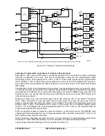
CDS240-MOTR-A-BE MOTOR PROTECTION LOGIC
The Motor Protection (CDS240-MOTR-A-BE) scheme provides high-speed differential and multiple layers
of instantaneous and time overcurrent protection for large motors. This scheme protects against stator
phase and ground faults, locked rotor, jam, thermal overload, and unbalanced current. Basic frequent
starting protection is also provided. Virtual control switch logic is used for local or remote control and can
be used to replace the equivalent panel control switches.
The control switch elements are referred to as virtual because they have no physical form, they exist only
in logic form, and they can only be operated via the ASCII command interface or the front panel. When
Virtual Control Switch 143 is on or enabled, motor starting is determined by speed switch. When off or
disabled, starting is determined by current detector set at 85% of locked rotor current. The Virtual Control
Switch 243 is used to customize the protection for high or low starting inertia applications. When high is
selected, 150TP is blocked, and 151P is enabled for locked rotor protection. The user may choose to
eliminate the use of external switches, as the virtual switches are fully functional equivalents of their
physical counterparts.
Figure 8-13 is a one-line drawing and Figure 8-14 is a logic drawing. Both represent the settings shown in
Table 8-31. In Table 8-31, the user can see the protection and control elements that are enabled for the
CDS240-MOTR-A-BE application and how the elements are logically wired together (equations). If the
user should decide to build on this scheme, all elements required for a more detailed application are
available through programming. For programming details, refer to Section 7,
BESTlogic Programmable
Logic.
Содержание BE1-CDS240
Страница 1: ...INSTRUCTION MANUAL FOR CURRENT DIFFERENTIAL SYSTEM BE1 CDS240 Publication 9365200990 Revision F 12 08 ...
Страница 2: ......
Страница 8: ...vi BE1 CDS240 Introduction 9365200990 Rev F This page intentionally left blank ...
Страница 38: ...1 28 BE1 CDS240 General Information 9365200990 Rev F This page intentionally left blank ...
Страница 40: ...ii BE1 CDS240 Quick Start 9365200990 Rev F This page intentionally left blank ...
Страница 74: ...3 22 BE1 CDS240 Input and Output Functions 9365200990 Rev F This page intentionally left blank ...
Страница 152: ...ii BE1 CDS240 Metering 9365200990 Rev F This page intentionally left blank ...
Страница 208: ...ii BE1 CDS240 BESTlogic Programmable Logic 9365200990 Rev F This page intentionally left blank ...
Страница 210: ...Figure 7 1 BESTlogic Function Blocks page 1 of 5 7 2 BE1 CDS240 BESTlogic Programmable Logic 9365200990 Rev F ...
Страница 211: ...Figure 7 2 BESTlogic Function Blocks page 2 of 5 9365200990 Rev F BE1 CDS240 BESTlogic Programmable Logic 7 3 ...
Страница 212: ...Figure 7 3 BESTlogic Function Blocks page 3 of 5 7 4 BE1 CDS240 BESTlogic Programmable Logic 9365200990 Rev F ...
Страница 213: ...Figure 7 4 BESTlogic Function Blocks page 4 of 5 9365200990 Rev F BE1 CDS240 BESTlogic Programmable Logic 7 5 ...
Страница 214: ...Figure 7 5 BESTlogic Function Blocks page 5 of 5 7 6 BE1 CDS240 BESTlogic Programmable Logic 9365200990 Rev F ...
Страница 222: ...7 14 BE1 CDS240 BESTlogic Programmable Logic 9365200990 Rev F This page intentionally left blank ...
Страница 226: ...iv BE1 CDS240 Application 9365200990 Rev F This page intentionally left blank ...
Страница 238: ...Figure 8 3 Typical One line Diagram for CDS240 BA87 B BE 8 12 BE1 CDS240 Application 9365200990 Rev F ...
Страница 262: ...Figure 8 11 Typical One line Diagram for CDS240 BSBU A BE 8 36 BE1 CDS240 Application 9365200990 Rev F ...
Страница 286: ...ii BE1 CDS240 Security 9365200990 Rev F This page intentionally left blank ...
Страница 290: ...9 4 BE1 CDS240 Security 9365200990 Rev F This page intentionally left blank ...
Страница 292: ...ii BE1 CDS240 Human Machine Interface 9365200990 Rev F This page intentionally left blank ...
Страница 296: ...Figure 10 4 BE1 CDS240 Menu Tree Control Branch 10 4 BE1 CDS240 Human Machine Interface 9365200990 Rev F ...
Страница 298: ...Figure 10 6 BE1 CDS240 Menu Tree Reports Branch 10 6 BE1 CDS240 Human Machine Interface 9365200990 Rev F ...
Страница 300: ...Figure 10 8 BE1 CDS240 Menu Tree Protection Branch 2 of 2 10 8 BE1 CDS240 Human Machine Interface 9365200990 Rev F ...
Страница 301: ... Figure 10 9 BE1 CDS240 Menu Tree General Settings Branch 9365200990 Rev F BE1 CDS240 Human Machine Interface 10 9 ...
Страница 306: ...10 14 BE1 CDS240 Human Machine Interface 9365200990 Rev F This page intentionally left blank ...
Страница 308: ...ii BE1 CDS240 ASCII Command Interface 9365200990 Rev F This page intentionally left blank ...
Страница 342: ...11 34 BE1 CDS240 ASCII Command Interface 9365200990 Rev F This page intentionally left blank ...
Страница 349: ...Figure 12 5 Horizontal Rack Mount Front View 9365200990 Rev F BE1 CDS240 Installation 12 5 ...
Страница 351: ...Figure 12 8 Vertical Panel Mount L size Front View 9365200990 Rev F BE1 CDS240 Installation 12 7 ...
Страница 361: ...Figure 12 17 Typical DC Connection Diagrams 9365200990 Rev F BE1 CDS240 Installation 12 17 ...
Страница 365: ...Figure 12 23 BE1 CDS240 Percentage Differential Bus Protection 9365200990 Rev F BE1 CDS240 Installation 12 21 ...
Страница 372: ...12 28 BE1 CDS240 Installation 9365200990 Rev F This page intentionally left blank ...
Страница 468: ...13 92 BE1 CDS240 Testing and Maintenance 9365200990 Rev F This page intentionally left blank ...
Страница 512: ...14 42 BE1 CDS240 BESTCOMS Software 9365200990 Rev F This page intentionally left blank ...
Страница 514: ...ii BE1 CDS240 Time Overcurrent Characteristic Curves 9365200990 Rev F This page intentionally left blank ...
Страница 538: ...ii BE1 CDS240 Overexcitation 24 Inverse Time Curves 9365200990 Rev F This page intentionally left blank ...
Страница 544: ...ii BE1 CDS240 Terminal Communication 9365200990 Rev F This page intentionally left blank ...
Страница 550: ...ii BE1 CDS240 Settings Calculations 9365200990 Rev F This page intentionally left blank ...
Страница 578: ...D 28 BE1 CDS240 Settings Calculations 9365200990 Rev F This page intentionally left blank ...
Страница 579: ......
Страница 580: ...ROUTE 143 BOX 269 HIGHLAND IL 62249 USA http www basler com info basler com PHONE 1 618 654 2341 FAX 1 618 654 2351 ...


