


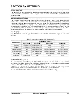
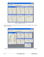


Retrieving Virtual Selector Switches Status from the Relay
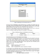
The state of each virtual selector switch can be determined from the optional HMI Screen 1.4.3,
\STAT\OPER\43. This information is also available through the ASCII command interface by using the
RG-STAT command and on BESTCOMS
Metering
screen. See Section 6,
Reporting and Alarm
Functions, General Status Reporting
, for more information.
HMI Screens 2.1.1 through 2.1.8 provide switch control and can also display the current status of their
respective switches. ASCII command CO-x43 returns the state of each virtual selector switch in a read-
only mode. See the previous Example 1.
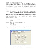
101 - Virtual Breaker Control Switches
Virtual breaker control switches (shown in Figure 4-67) provide manual control of a circuit breaker or
switch without using physical switches and/or interposing relays. Both local and remote control is
possible. A virtual switch can be used instead of a physical switch to reduce costs with the added benefit
that the virtual switch can be operated both locally from the HMI and remotely from a substation computer
or modem connection to an operator's console. The BE1-CDS240 relays provide four Virtual Breaker
Control Switches (101, 1101, 2101, and 3101).
Figure 4-67. Virtual Breaker Control Switch Logic Block
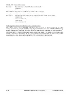
The virtual breaker control switch emulates a typical breaker control switch with a momentary close,
spring return, trip contact (output 101T), a momentary close, spring return, close contact (output 101C),
When the virtual control switch is controlled to trip, the 101T output pulses TRUE (closed) for
101SC output goes FALSE (open). When the virtual control
and a slip contact (output 101SC). The slip contact output retains the status of the last control action. That
is, it is FALSE (open) in the after-trip state and TRUE (closed) in the after-close state. Figure 4-68 shows
the state of the 101SC logic output with respect to the state of the 101T and 101C outputs.
approximately 200 milliseconds and the
switch is controlled to close, the 101SC output pulses TRUE (closed). The status of the slip contact
output is saved to nonvolatile memory so that the relay will power up with the contact in the same state as
when the relay was powered down.
Figure 4-68. Virtual Breaker Control Switch State Diagram
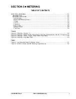
BESTlogic Settings for Virtual Breaker Control Switches
BESTlogic settings are made from the
BESTlogic Function Element
screen in BESTCOMS. Figure 4-69
illustrates the BESTCOMS screen used to select BESTlogic settings for the 101 V
irtual Breaker Control
Switch
element. To open the
BESTlogic Function Element
screen for the 101
Virtual Breaker Control
Switch
element, select
Virtual Switches
from the
Screens
pull-down menu. Then select the
101 – 1101 –
2101 – 3101
tab. Next, select the
BESTlogic
button for the Virtual Breaker Control Switch to be edited.
Alternately, settings may be made using the SL-x101 ASCII command (where x = blank, 1, 2, or 3).
4-70
BE1-CDS240 Protection and Control
9365200990 Rev F
Содержание BE1-CDS240
Страница 1: ...INSTRUCTION MANUAL FOR CURRENT DIFFERENTIAL SYSTEM BE1 CDS240 Publication 9365200990 Revision F 12 08 ...
Страница 2: ......
Страница 8: ...vi BE1 CDS240 Introduction 9365200990 Rev F This page intentionally left blank ...
Страница 38: ...1 28 BE1 CDS240 General Information 9365200990 Rev F This page intentionally left blank ...
Страница 40: ...ii BE1 CDS240 Quick Start 9365200990 Rev F This page intentionally left blank ...
Страница 74: ...3 22 BE1 CDS240 Input and Output Functions 9365200990 Rev F This page intentionally left blank ...
Страница 152: ...ii BE1 CDS240 Metering 9365200990 Rev F This page intentionally left blank ...
Страница 208: ...ii BE1 CDS240 BESTlogic Programmable Logic 9365200990 Rev F This page intentionally left blank ...
Страница 210: ...Figure 7 1 BESTlogic Function Blocks page 1 of 5 7 2 BE1 CDS240 BESTlogic Programmable Logic 9365200990 Rev F ...
Страница 211: ...Figure 7 2 BESTlogic Function Blocks page 2 of 5 9365200990 Rev F BE1 CDS240 BESTlogic Programmable Logic 7 3 ...
Страница 212: ...Figure 7 3 BESTlogic Function Blocks page 3 of 5 7 4 BE1 CDS240 BESTlogic Programmable Logic 9365200990 Rev F ...
Страница 213: ...Figure 7 4 BESTlogic Function Blocks page 4 of 5 9365200990 Rev F BE1 CDS240 BESTlogic Programmable Logic 7 5 ...
Страница 214: ...Figure 7 5 BESTlogic Function Blocks page 5 of 5 7 6 BE1 CDS240 BESTlogic Programmable Logic 9365200990 Rev F ...
Страница 222: ...7 14 BE1 CDS240 BESTlogic Programmable Logic 9365200990 Rev F This page intentionally left blank ...
Страница 226: ...iv BE1 CDS240 Application 9365200990 Rev F This page intentionally left blank ...
Страница 238: ...Figure 8 3 Typical One line Diagram for CDS240 BA87 B BE 8 12 BE1 CDS240 Application 9365200990 Rev F ...
Страница 262: ...Figure 8 11 Typical One line Diagram for CDS240 BSBU A BE 8 36 BE1 CDS240 Application 9365200990 Rev F ...
Страница 286: ...ii BE1 CDS240 Security 9365200990 Rev F This page intentionally left blank ...
Страница 290: ...9 4 BE1 CDS240 Security 9365200990 Rev F This page intentionally left blank ...
Страница 292: ...ii BE1 CDS240 Human Machine Interface 9365200990 Rev F This page intentionally left blank ...
Страница 296: ...Figure 10 4 BE1 CDS240 Menu Tree Control Branch 10 4 BE1 CDS240 Human Machine Interface 9365200990 Rev F ...
Страница 298: ...Figure 10 6 BE1 CDS240 Menu Tree Reports Branch 10 6 BE1 CDS240 Human Machine Interface 9365200990 Rev F ...
Страница 300: ...Figure 10 8 BE1 CDS240 Menu Tree Protection Branch 2 of 2 10 8 BE1 CDS240 Human Machine Interface 9365200990 Rev F ...
Страница 301: ... Figure 10 9 BE1 CDS240 Menu Tree General Settings Branch 9365200990 Rev F BE1 CDS240 Human Machine Interface 10 9 ...
Страница 306: ...10 14 BE1 CDS240 Human Machine Interface 9365200990 Rev F This page intentionally left blank ...
Страница 308: ...ii BE1 CDS240 ASCII Command Interface 9365200990 Rev F This page intentionally left blank ...
Страница 342: ...11 34 BE1 CDS240 ASCII Command Interface 9365200990 Rev F This page intentionally left blank ...
Страница 349: ...Figure 12 5 Horizontal Rack Mount Front View 9365200990 Rev F BE1 CDS240 Installation 12 5 ...
Страница 351: ...Figure 12 8 Vertical Panel Mount L size Front View 9365200990 Rev F BE1 CDS240 Installation 12 7 ...
Страница 361: ...Figure 12 17 Typical DC Connection Diagrams 9365200990 Rev F BE1 CDS240 Installation 12 17 ...
Страница 365: ...Figure 12 23 BE1 CDS240 Percentage Differential Bus Protection 9365200990 Rev F BE1 CDS240 Installation 12 21 ...
Страница 372: ...12 28 BE1 CDS240 Installation 9365200990 Rev F This page intentionally left blank ...
Страница 468: ...13 92 BE1 CDS240 Testing and Maintenance 9365200990 Rev F This page intentionally left blank ...
Страница 512: ...14 42 BE1 CDS240 BESTCOMS Software 9365200990 Rev F This page intentionally left blank ...
Страница 514: ...ii BE1 CDS240 Time Overcurrent Characteristic Curves 9365200990 Rev F This page intentionally left blank ...
Страница 538: ...ii BE1 CDS240 Overexcitation 24 Inverse Time Curves 9365200990 Rev F This page intentionally left blank ...
Страница 544: ...ii BE1 CDS240 Terminal Communication 9365200990 Rev F This page intentionally left blank ...
Страница 550: ...ii BE1 CDS240 Settings Calculations 9365200990 Rev F This page intentionally left blank ...
Страница 578: ...D 28 BE1 CDS240 Settings Calculations 9365200990 Rev F This page intentionally left blank ...
Страница 579: ......
Страница 580: ...ROUTE 143 BOX 269 HIGHLAND IL 62249 USA http www basler com info basler com PHONE 1 618 654 2341 FAX 1 618 654 2351 ...


