-63-
10.
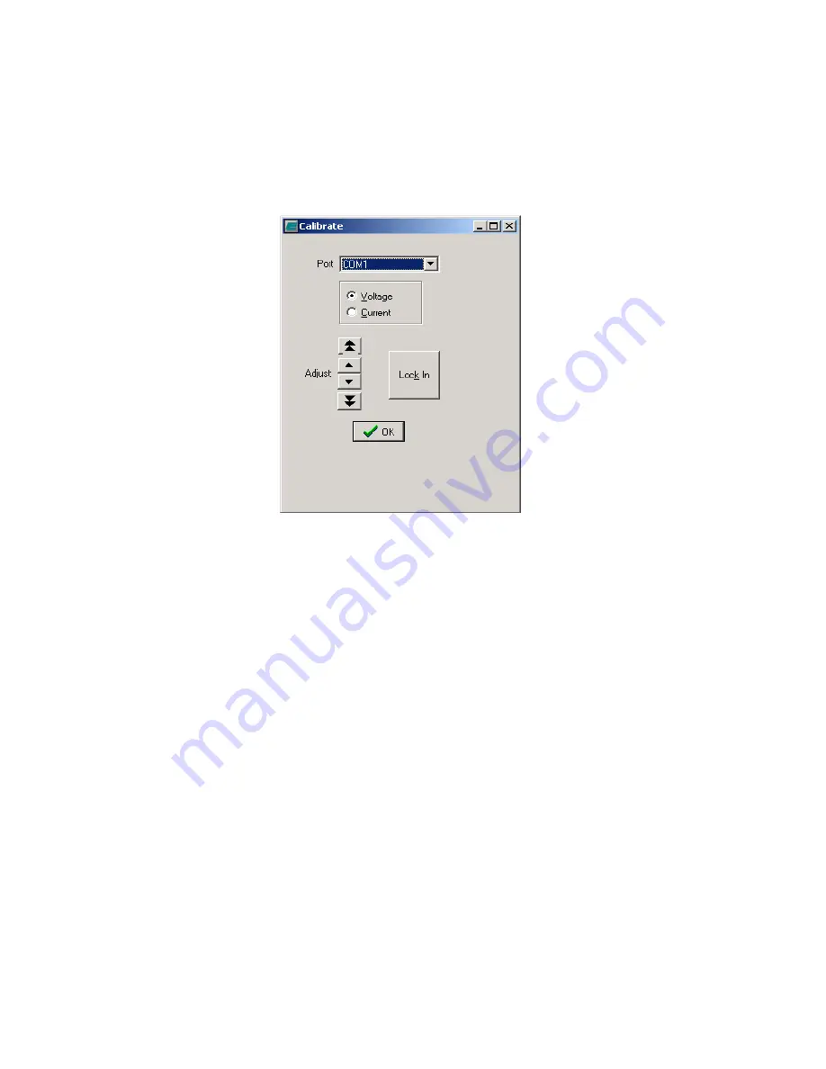
Measure the voltage or current from the Analog Output Module. For a voltage output there
should be a potential of 10 volts across the +V out and –V out terminals. For a current
output there should be a 20mA current flowing between the +I out and –I out terminals
(ExtPWR and –V out if External Power is utilized – see section on Optional External Power).
Figure A-19
Adjusting Calibration of Analog Output Module:
To adjust the calibration of the Analog Output Module, follow the steps outlined in the previous
section. Adjustments are made by the up and down arrows on the calibration menu box. Adjust
the calibration so the output from the module is either 10.000 volts or 20.000mA, depending on
the mode selected. Once the output is correct, press the “Lock In” button on the calibration
menu box. None of the adjustments will be stored until the Lock In button is pressed. There is
no need to adjust the zero calibration on the Analog Output Module.
Содержание EXACTUS
Страница 2: ...This page blank ...
Страница 23: ... 19 Figure 12 All Probes display Figure 13 Analog Output Setup Window ...
Страница 37: ... 33 Figure 14 Lens Collection Optics Pyrometer ...
Страница 38: ... 34 Figure 15 Probe with Lightpipe ...


