background image


FWG09I Assembly instructions 


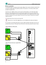
Connecting the alarm buttons 

The FWG09 offers the possibility to connect two alarm buttons, alarm button 1 and alarm button 2. 
Both buttons can be configured independently of each other as NO or NC contact. It is intended that 
the alarm button in the car is connected to alarm button 1 and one or more buttons on or under the 
car are connected to alarm button 2. 

Only potential-free contacts may be connected.


In order to monitor the cable up to a button with NO contacts, you can attach a 1K resistor to the 
button and set the corresponding button to "

cable break monitored

”. 

Input for misuse signal 

Various functions can be triggered via a voltage at the misuse input of 10-48V DC or 10-42V AC. 
These can be set in the service menu, see page 9. 

Misuse 

A signal can be connected to indicate that the alarm has been misused. This is only evaluated with 
the car alarm button 1. A distinction can be made as to whether a “

misuse

” message should be sent 

to the call center or whether there should be no reaction at all. For the purpose of an emergency call 
test, an emergency call is triggered in both cases after 30 seconds of continuously pressing the alarm 
button in the car. 

Fire alarm 

There is also the possibility of an endless announcement “

Fire alarm, leave cabin immediately

” This 

feature can also be used during installation to test the misuse signal. 

Passing on battery problems 

 In accordance with EN81-28, the FWG09 indicates faults in its own battery by blinking the 
pictograms. In order to be able to use this function for the elevator control as well, there is the 
possibility of triggering the blinking of the pictograms through voltage or lack of voltage. 

Malfunction warning 

An applied voltage can also be sent to the call center as a general error message. 


Содержание FWG09

Страница 1: ...Hotline phone 040 790 261 790 040 529 811 30 040 529 811 31 Website https base engineering com Version 2023 06 28 1 FWG09 Assembly instructions Connections with adapter board...

Страница 2: ...FWG09I Assembly instructions 2 Direct connections without adapter board...

Страница 3: ...rect the sound outlet opening of the FWG09 to the side of the shaft wall never up The connectors should point downwards Avoid sound reflections on plane surfaces that are too close keep at least 20cm...

Страница 4: ...pter board pull the orange plug 2 Press the buttons Option and Option simultaneously A shutdown sound plays This is important as otherwise the unit will continue to run on battery mode and the battery...

Страница 5: ...ns of an external power supply This can be up to 60 volts the maximum current is 100mA The switch output lies at position B C the negative terminal is always switched The ground of the power supply of...

Страница 6: ...xternal power supply This can be up to 60 volts the maximum current is 100mA The switch output lies at position B D the negative terminal is always switched The ground of the power supply of the LEDs...

Страница 7: ...connected to indicate that the alarm has been misused This is only evaluated with the car alarm button 1 A distinction can be made as to whether a misuse message should be sent to the call center or...

Страница 8: ...by outputting a potential free illustration of the alarm button replacing the missing second level The internal circuit of the FWG09 is used to switch the connected alarm button to the recognition cir...

Страница 9: ...m is reported as a normal alarm On misused alarm is reported as such Suppressed misused alarm is not reported at all Fire alarm As long as voltage is supplied an announcement is played to leave the li...

Страница 10: ...is dialed before each telephone number A pause of 1 2 seconds is included after the 9 9 without pause A 9 is dialed before each telephone number The entire number including 9 is dialed in a row witho...

Страница 11: ...pictograms alarm button and speaker optional microphone for In wall 200400001480 Panel 3 with emergency light and pictograms for On wall 200400001460 Panel 4 with emergency light and pictograms for I...

Страница 12: ...hind the elevator panel without opening the panel you can also access the service menu via DTMF To do this call the device and type in Object Car 0 after the answer tone for example 7191710 for the de...

Страница 13: ...8 The software variant 1 complies with EN81 28 Variants 2 2A 3 3A and 3B are not compliant with EN81 28 and are thus to be set at one s own responsibility Technical requirements When choosing no evalu...

Страница 14: ...esponds to all sent DTMF commands regardless of this Program 3A Same as program 3 the object number is announced twice before establishing the voice connection Program 3B Like program 3 but a voice co...

Страница 15: ...atively you can temporarily change the program variant to 2 in the service menu while programming If the master PIN is successfully entered the object number is announced Individual units or car 1 for...

Страница 16: ...ou then enter the PIN with a both in front and behind or Car the announcement Messages cleared is made for technical messages This means that the message has been successfully transmitted for that par...

Страница 17: ...r 1 And the instruction Please enter 1 to accept the emergency call 3 Establish a voice communication 1 Response from unit Voice connection 1 on Please enter 0 to terminate the voice connection 4 Spea...

Страница 18: ...pplied at the misuse input Recommendations for action Establish voice communication and respond accordingly Emergency over car n Programs 1 2 2A An active emergency call has been marked as finished on...

Страница 19: ...The battery is actually missing or is inserted incorrectly Recommendations for action Take the lift out of operation Battery broken car n Programs 1 2 2A The battery can no longer be charged or in its...

Страница 20: ...r more cars using the code transmitter This is an older method to connect via telephone to units that only support call center communication Recommendations for action Document the message with date a...

Страница 21: ...onfuse with Battery broken car n Recommendation for action Arrange for battery replacement for the GSM10 GSM13 Module within one week T V Certification The conformity of FWG09 to EN81 28 has been cert...

Страница 22: ...of the EMC Directive 2014 30 EU Elevator Directive 2014 33 EU including the changes which applied at the time of the declaration The following harmonised standards have been applied Electromagnetic C...

Страница 23: ...er risk Severity of the potential impact on operations financial impact or health Likelihood of occurrence Operations low Operations middle Operations high Financial low Financial middle Financial hig...

Страница 24: ...FWG09I Assembly instructions 24 This page is intentionally left blank...

Страница 25: ...erwise also generate All these messages are reported to the receiving station and must be acknowledged via the DTMF commands on the telephone keypad because the emergency call system will continue to...

Страница 26: ...the internal emergency power supply is no longer known For the reasons set out above this program version is not compatible with the obligations of an operator even with supplementary measures and th...

Отзывы: