FWG09I Assembly instructions
3
Advice on VoIP telephone systems
Before operating with telephone systems based on the Internet protocol IP, please set the following
parameters: The G.711a codec should be used. The transmission must be transparent, meaning that
measures to reduce bandwidth such as detecting whether someone is speaking (voice/silence
detection), noise suppression and echo cancellation or similar must be deactivated to connect the
FWG09. The conversion of faxes according to T.38 must also be prevented. If necessary, establish
contact between the person responsible for the telephone system and base engineering gmbh.
Surroundings
The FWG09 is only approved for use in a temperature range from 0°C to +40°C.
Installation
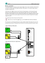
When connecting the adapter board please wear protection gloves.
With the supplied mounting kit the installation on the car roof is the easiest and fastest option.
The position of the FWG09 is important for the quality of the voice connection. Please consider the
following points:
Keep the FWG09 away from car ventilators, ballasts for fluorescent tubes or door motors.
Pay attention to sufficiently large sound openings to the car space, use ventilation openings
etc.
Preferably direct the sound outlet opening of the FWG09 to the side of the shaft wall; never
up. The connectors should point downwards.
Avoid sound reflections on plane surfaces that are too close, keep at least 20cm distances.
If there is distortion during the speech connection from the loudspeaker, use the service
menu to reduce the speaker volume.
The FWG09 should be protected from dripping water, if possible with the connectors
pointing downwards. If protection according to IPX1 is required at the installation site, use
watertight tape on the connector at the back of the device next to the object number sticker.
The housing then fulfills the requirements of IPX1.
The FWG09 can also be mounting behind the control panel. It should be noted that it needs to be
protected against vandalism.
Commissioning
1.
Ensure that the batteries are inserted.
Please pay attention to the correct polarity, as the unit is not supplied with backup
power if the batteries are inserted the wrong way around.
2.
Connect a power supply of 10–28V DC voltage or use a suitable plug-in power supply. The
external power supply must be able to supply 600mA of current and should not be supplied
with emergency power, since the FWG09 has its own battery power supply.
3.
Configure the FWG09 using the service menu: Usually set the alarm button types or switch to
gate keeper mode.
4.
Connect the telephone line. Please use a twisted pair cable if possible!


