INSTALLATION AND USE MANUAL
SERVO DRIVE TYPE
– DB21
M.DRIVE.DB-21.GEN.ENG
Ed.
2022
Rev.11
Pag.
12 di 34
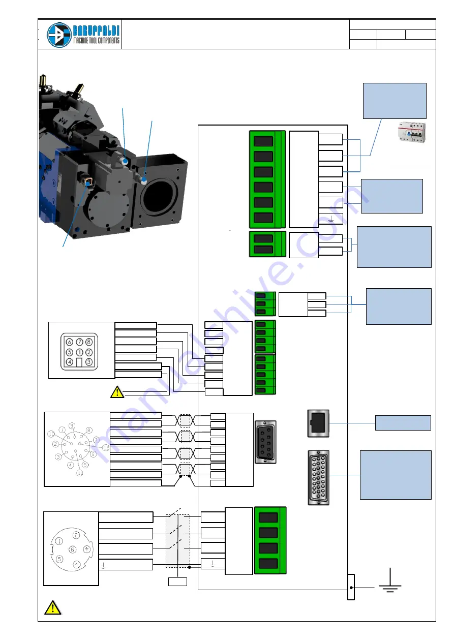
4.4
LINEA
LEONARDO
–
TC/TCMA/TCMR/TCMQ
(STANDARD
WITH
PLUG-IN
CONNECTORS)
X1
X4
X3
2
X2
Power supply
10/-15%
10/-15%
P
min
=2KVA
(Shielded Cable)
Auxiliary supply
24Vdc ±10%
Circuit consumption is 500mA.
Total consumption depend of
relais/electrovalve
(Shielded Cable)
Electrovalve
Use auxiliary relays to
pilotate the
electrovalve.
I
max
Output=2,5A
(Shielded Cable)
I/O
Digital I/O
connect to PLC.
Details at page N°6.
All signals are
optoisolated.
After a short circuit is
necessary to switch
off the auxiliary
supply
J2
X5
U
V
W
U Motor phase
V Motor phase
W Motor phase
PE Motor ground
C Shield
1
2
3
4
5
6
7
8
9
LI.15
OP
LI.16
OP
+24v
OP
LI.12
LI.13
LI.14
Brown 10 +24V
Blue 11 0V
2 Turret Unlock
3 Turret Lock
4 Zero Sensor
L1
L2
L3
+
-
100c-MOTOR
(Shielded Cable (4x1.5mm²))
Serial Port
+24v
OP
LO.15
LO.16
OP
1
5
2
DB BUS (output)
DO NOT USE
5 +24V
6 0V
102b-TURRET
(Shielded Cable - sensors 24Vdc no pnp LMax=200mA)
7 Thermal switch
8 Thermal switch
1 ref
2 0 ref
3 0 cos
4 cos
5 sin
6 0 sin
9 Shield
100b-RESOLVER
& THERMAL SWITCH
(Shielded Cable 4x(2x0.25mm²))
7 Quicklock Unlock
8 Quicklock Lock
102b
–
Turret Connector (Sensors)
100b
–
Motor Connector Resolver
100c
–
Motor Connector Power
Only for TCMQ version:Direct
connection to the Machien PLC
Protection device RCD (with
differential protection I
d
=
300mA) type F
+
Thermal magnetic circuit
breake (16A) type C
SAFETY STOP
MACHINE GROUND
Do not install power contactor (or relais) on the input voltage of the drive (L1-L2-L3), it generates alarm on the drive.
For safety reasons it might be possible to put power contactor (or relais) on the phases between the motor and the drive (U-V-W), (e.g. to cut the power during
machine open door or emergency situation)
.


