background image


INSTALLATION AND USE MANUAL 

SERVO DRIVE TYPE 

– DB21  

M.DRIVE.DB-21.GEN.ENG 

Ed. 

2022 

Rev.11 

Pag. 

27 di 34 


13.2


COMPATIBILITY


WITH


PREVUIOUS


VERSIONS 


The drive DB-21 is compatible with all drives and motors previously used with brushless turrets. 
In case of replacing an old drive where the turret or motor are different from the current it's necessary 
execute the SETUP configuration following the procedure explained in the next chapters. 
 
The sequence of steps for the position request and general management of the dialogue between plc and drive 
is common and compatible among all drives. 
 
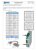
The installation of the new drive on CNC instead of a drive of previous versions to the model DMS08BF requires 
rewiring the connector J1 or the adoption of an adapter DB37 to DB26: ask details and price to Baruffaldi 
service or commercial department. 


13.2.1

 DRIVE AND MOTOR TIMELINE 


In case of drive replacement to DB-21 it is necessary also to replace the motor in case the 
turret has a Magnetic 5KHz or Lafert 5KHz motor 


13.2.2

 TURRET SERIAL NUMBER IDENTIFICATION 


Drive Model 

SA.01A.TB 

SA.02A.TB 

DMS08-BF 

BD21 

TB-Series  

serial n° 

0-1837 

(K2 model) 

1838-2330 

(K2 model) 

2331-3122 

(K2 model) 

3123-4272 

(K2 model) 

4273-6459 

(K5 model) 

6460-9952 

(K5 model) 

9952-14500 

(K5 model) 

14501


(K5-KL model) 

TAB-Series 

serial n° 


0-55 

(K3 model) 

56


(K3 model) 

TC-Series 

serial n° 


0


(KL model) 

Motor type 

Magnetic 

5KHz 

Lafert 5KHz 

Lafert 10KHz 

Baruffaldi MB21 10KHz 

Lafert 10KHzKL  


Baruffaldi MB22 10KHz 

(For TC series) 

2000 

2005 

2007 

2016 

2004 

2009 

2006 

2021 

Identification code 

Delivered with 

     tool holder disc 


Serial number 

Turret type 

Содержание DB-21

Страница 1: ...E DB 21 GEN ENG Ed 2022 Rev 11 Pag 1 di 34 INSTALLATION AND USE MANUAL Servo Drive type DB 21 Suitable for turrets models Linea Archimede TB TBMA TBMR Linea Michelangelo TAB Linea Leonardo TC TCMA TCM...

Страница 2: ...PERATIVE MODE __________________________________________________________ 14 5 6 POSITION REQUIRED ________________________________________________________ 14 6 DIPSWITCH SETTING FOR TURRET TYPE SELECT...

Страница 3: ...nce is not performed correctly and regularly Functional changes of any type are brought without manufacturer s consent Original spare parts are not used This symbol highlights critical operations a wr...

Страница 4: ...hat the converter cannot work without nominal temperature range 0 40 C Relative air humidity must be kept below 90 with no condensation A 150mm clearance area must be considered over and under the dri...

Страница 5: ...cables must be shielded and connected to the ground in order to prevent EMC problems TURRET CABLE INSTALLATION It is necessary to separate the turret cables from other machines cables e g separate ca...

Страница 6: ...nal Current 6Arms Method of current control SPWM chopper frequency 3 10 KHz Motor control method Torque control speed control angular position control Clamp resistance 47 50W Protection grade IP 20 LI...

Страница 7: ...c and drives details page 6 X5 OUTPUT MOTOR U V W T 3 phase shielded cable min 1 5mm2 with ground J2 INPUT ANGULAR POSITION TRANSDUCER Use cable with shielded twisted pairs and external shield min 0 2...

Страница 8: ...X4 J2 X3 RS485 J1 X3 Software supervisior only for Service support The using of auxilliary relais between the drive and the electrovalves is mandatory X4 connections Lo 15 Lo 16 OP must be conencted d...

Страница 9: ...llow 7 sin Blue 8 0 sin Pink 9 Shield 1 2 3 4 5 6 7 8 9 LI 15 OP LI 16 OP 24v OP LI 12 LI 13 LI 14 Brown 10 24V Blue 11 0V Black 12 Turret Unlock Black 13 Turret Lock Black 14 Zero Sensor Brown 10 24V...

Страница 10: ...ed 6 cos Yellow 7 sin Blue 8 0 sin Pink 9 Shield 1 2 3 4 5 6 7 8 9 LI 15 OP LI 16 OP 24v OP LI 12 LI 13 LI 14 Brown 10 24V Blue 11 0V Black 12 Turret Unlock Black 13 Turret Lock Black 14 Zero Sensor L...

Страница 11: ...6 cos Yellow 7 sin Blue 8 0 sin Pink 9 Shield 1 2 3 4 5 6 7 8 9 LI 15 OP LI 16 OP 24v OP LI 12 LI 13 LI 14 Brown 10 24V Blue 11 0V Black 12 Turret Unlock Black 13 Turret Lock Black 14 Zero Sensor L1 L...

Страница 12: ...Unlock 3 Turret Lock 4 Zero Sensor L1 L2 L3 100c MOTOR Shielded Cable 4x1 5mm Serial Port 24v OP LO 15 LO 16 OP 1 5 2 DB BUS output DO NOT USE 5 24V 6 0V 102b TURRET Shielded Cable sensors 24Vdc no p...

Страница 13: ...not in reset mode mode bit off The position feedback is in binary code see table at left without the parity bit 5 3 ALARMS N 5 binary outputs communicate the presence of an active alarm In order to f...

Страница 14: ...DRIVE TYPE DB21 M DRIVE DB 21 GEN ENG Ed 2022 Rev 11 Pag 14 di 34 It is recommended to manage the parity bit using the Boolean function EXOR available in all PLCs applied to the position bit 5 5 OPER...

Страница 15: ...transmission ratio T R number of stations and dynamic profile in this case a red label will be applies on the drive In order to replace the drive will be necessary reset the profile via p c on the ne...

Страница 16: ...procedure is performed in the factory during the test drive turret and need to be repeated only in the case that the drive or the motor are substituted or when the motor is removed from the turret Seq...

Страница 17: ...inquiry Position Error 6 x after position inquiry ZERO SEARCH Zero search also hidden has to be performed after switch on the drive or a reset ZERO SEARCH Operative mode 1 Position required 0 Wait 50...

Страница 18: ...ions pre setting tool replacement For each START command the turret will perform a jump of 1 station in the direction of rotation set Mod 4 1 position clockwise rotation Mod 4 2 position counter clock...

Страница 19: ...VOLTAGE WOULD DAMAGE IRREVERSIBLY THE UNIT THE DRIVE ARRIVE WITH THE TURRET PRE SET IN CASE OF WRONG PRESELECTION OF THE TURRET SIZE AND TYPE CONTACT BARUFFALDI Sequence of operations N 2 VOLTAGE SETT...

Страница 20: ...if set K5 Sequence of operations N 3 1 Drive OFF 24Vdc Off 2 Turret Locked on the first position 4 Select the turret voltage see operations sequence 1 type and number of positions as the table below...

Страница 21: ...on required 3 Engine stays in position control T Minimum time before the new position request TB TBH TC 120 160 T 2 TB TBH TC 200 250 T 4 TAB 210 265 TB320 400 T 5 TAB 340 440 1 Engagement of the prox...

Страница 22: ...ps and goes straight to the position required T Minimum time before the new position request TB TBH TC 120 160 T 2 TB TBH TC 200 250 T 4 TAB 210 265 TB320 400 T 5 TAB 340 440 2 Management of the proxi...

Страница 23: ...y switch Li 12 Off Li 13 Off 10 4 2 Lock proximity switch in short circuit Li 12 Li 13 On 11 10 4 3 The unlock proximity switch signal has been lost during rotation Li 12 Off 12 0 Turret Unlocking Ala...

Страница 24: ...ute sensor alarm Contact Baruffaldi service 3 4 3 6 A5 1 A6 0 Radiator thermal alarm Contact Baruffaldi service 4 0 During unlocking the turret stays closed Li 12 Off Li 13 On 4 After 30 from the unlo...

Страница 25: ...ve gives a command for locking the turret if the lock proximity switch Li 13 is off the alarm is activated Check the functionality of proximity switch Check the hydraulic pneumatic circuit Check the e...

Страница 26: ...60 Motor phases value UV VW UW 4 5 Resolver value 34 40 56 60 78 60 Motor phases value UV VW UW 4 5 Resolver value 34 40 56 60 78 60 Motor phases value UV VW UW 4 5 8 1 Motor PTC 13 This alarm is act...

Страница 27: ...ires rewiring the connector J1 or the adoption of an adapter DB37 to DB26 ask details and price to Baruffaldi service or commercial department 13 2 1 DRIVE AND MOTOR TIMELINE In case of drive replacem...

Страница 28: ...h 3 Set to ON dipswitch n 9 turret setting mode 4 Set the input motor and turret type as the tables below 5 Turn ON the drive auxiliary supply 24V dc Display shows AF 6 Set to on the dipswitch n 10 an...

Страница 29: ...4 if set K3 TAB 340 440 8 if set K5 6 if set K3 Custom 12 if set K5 24 if set K5 Sequence of operations N 3 1 With the drive still power OFF 24Vdc Off 2 Set ON the dipswitches according to the turret...

Страница 30: ...ge not set up incorrect or not connected EE Resolver failure 8 0 at startup Locking Error 5 x after position inquiry Position Error 6 x after position inquiry 3 Switch ON the drive 4 Check on the disp...

Страница 31: ...rret rotate the motor gear aligning Y mark as shown in the picture below opposite to the X mark Fit new motor 3 on turret housing and check that O ring is properly fitted in its own seat While locking...

Страница 32: ...otor gear aligning Y mark as shown in the picture below opposite to the X mark Fit new motor 3 on turret housing and check that O ring is properly fitted in its own seat While locking screws 2 slightl...

Страница 33: ...by the turret at the end zero research also hidden zero research This procedure is performed in the factory during the test drive turret and need to be repeated only in the case that the drive or the...

Страница 34: ...del DMS 08 POSITION FEEDBACK The outputs of the position feedback are not present in the drive before type DMS08 BF These outputs communicate the station of the turret and gives a supplementary inform...

Отзывы: