12
ENGLISH
GB
When the device is to be
installed near the walls, partitions,
kitchen cabinets, decorative elements,
etc., they must be made from non-
flammable materials or covered with
suitable non-flammable materials.
Internal installation of the gas supply and the rooms
in which the device is housed must comply with the
local regulations applicable in the country in which
the device is used (Regulation of 12th of July 1996
and UNI-CIG 87/23).
In order to ensure proper gas burning in the
burners the required volume of air, i.e. approx. 2
cubic meters per hour for every kW of installed
power, must be supplied.
8.3.
Extraction of fumes
The fumes from the stove should be continuously
extracted with use of kitchen extraction hoods
connected to the extraction dusts or stacks, or
extracting directly outside. When no kitchen
extraction hood may be installed, use the fan for
direct extraction outside, connected in such way
that lock of suction fan interrupts the gas supply.
Installation of stoves of type “
A
” does not
envisage connection to the fume exhaust system,
but to the appropriate extraction hood which
removes the fumes outside.
8.4.
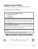
Installation of the appliance in a line
To fix the appliance in a line (neighbouring) follow
the steps:
Dismantle the control panel, and remove the cast
iron frame from the chimney if necessary.
Apply the sealing tape (
A
) onto the joining sides.
Place the appliances next to each other and in a
horizontal position (by adjusting the feet).
Connect the appliances with the joining elements.
8.5.
Gas connection (service technician)
The gas connection must be performed in
compliance with the applicable regulations.
Before connecting the device check the technical
data, type of gas, working pressure and flow rate
which are provided on the rating plate.
The installation is performed by connecting the
connection pipe of the device with a pipe of the
gas distribution network. The cut-off valve must be
installed on the connection to shut the gas supply
off if necessary.
A
A
B
C
C
Содержание FA092M00
Страница 20: ...I ANLAGEN ATTACHMENTS ANNEXES ALLEGATI ANEXOS ANEXOS BIJLAGEN ZA CZNIKI...
Страница 21: ...II...
Страница 36: ...XVII NOTE...