BARTINGTON INSTRUMENTS
Page 27 of 61 OM1800/26
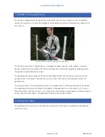
the operator should keep the centre of the assembly over a fixed point. This is most easily
achieved using the harness.
Note:
When the display requests that the sensors be moved to the opposite direction,
rotate the gradiometer through 180 degrees for the best result. Find N, S, E and W to
within a few degrees using a compass, which should then be removed to a safe distance.
Note:
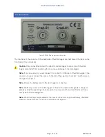
At each stage in the sequence of operations, the instrument will bleep and the
display will prompt the operator when a change in the position of the gradiometer is
required. After setting the required direction, the operator should press the green button –
equivalent to the
ENTER
key – and wait for the adjustment to be made.
Note:
If set-up is difficult due to a noisy magnetic environment, hold the entire system as
high up as is comfortable to perform the setup procedure and protect against interference
from the ground.
15.4.1. Procedure
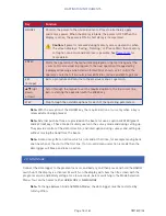
1. From the main menu, select
Adjust Gradiometer
. The initial display will prompt the operator to
Point arrows North
and Then Press Enter/PB
.
2. Align the assembly so the sensor arrows point north and the sensors are vertical, then press
the green push button. When the button is pressed, the instrument will take readings from
the sensors. It will then bleep and prompt the operator with the message
Point arrows South
and
Then Press Enter/PB
.
3. Rotate the gradiometer to point the arrows south. Press the green button when stable. The
gradiometer will then take a series of measurements and make corrections to the sensors in
turn.
4. Point the sensor arrows east and west as prompted by the display.
5. When prompted to invert the sensor, face west and rotate the beam so that the tops of the
sensors are now pointing vertically downward, and press the green button.
6. When prompted, restore the sensors to the normal position with the arrows pointing west. At
this point, both the vertical error and offset are adjusted.
7. Point the sensor arrows east, south and north again as prompted while further corrections
are made.
8. If all is well, the display will show
Set up finished
and prompt the operator to press the
ENTER
key or push button.
15.4.2. Adjustment
The above set-up procedure is carried out with the full-scale range set to 100nT by the program.
The results are displayed with a resolution of 0.01nT. If at any stage the program detects that
Содержание Grad601
Страница 1: ...Operation Manual for Grad601 Single Axis Magnetic Field Gradiometer System...
Страница 2: ......
Страница 59: ...BARTINGTON INSTRUMENTS Page 59 of 61 OM1800 26 Notes...
Страница 60: ...BARTINGTON INSTRUMENTS Page 60 of 61 OM1800 26...


