background image

BARTINGTON INSTRUMENTS


Page 50 of 61 OM1800/26

Ensure a magnetically quiet area is used: 

An area chosen to perform the adjustment should be 

examined using Scan mode first. A good set-up area has less than 0.5nT variation in magnetic 
gradient over a 1.5m x 1.5m area. Ensure you face in one direction for this test as directional 
errors will not yet have been removed. If readings are very high then the ground in the area may 
have magnetic content and another location should be used.

Coarse/fine ranges:


The adjustment cycle varies depending on whether you have selected the 

100nT or 1000nT range. If the process restarts at any point, it is because the set-up is being 
repeated in an alternate range. It is important to know how the equipment works so it is not 
misinterpreted as faulty behaviour. 

100nT Range:

 A set-up will be attempted in the 100nT range. If this fails then it will repeat 

the process in the 1000nT range. If successful in the 1000nT range, one further set-up will 
be attempted again in the 100nT range.

1000nT Range: 

A set-up will be attempted in the 1000nT range. If this is successful then a 

set-up will be attempted in the 100nT range.

High gradient readings: 

If the equipment is showing abnormally high values and the surrounding 

area is known to be magnetically quiet then there are several ‘fixes’ that can be attempted to 
bring it back to a normal level. The gradiometer should initially be set to the 1000nT range for 
these to work.

High Balance: 

Lift the gradiometer as high as you can above the ground, or stand on a non-

magnetic object, when carrying out the set-up process. This will lessen the impact of any 
ground signals and bring the level of magnetic field registered by the two sensors in each 
gradiometer closer together.

Horizontal Balance: 

This has a similar effect to the above test. Hold the gradiometer 

horizontal for the duration of the set-up process in order to bring the values back into a 
normal range.

Once these tests have been carried out, the Grad601 should then be set up once more in the 
normal fashion, and will be more likely to be successful.

If these suggestions do not prove helpful, please contact Bartington Instruments at 

support

@

bartington.com

 for further assistance.

21.2. Datalogger

The program for the Grad601 is held in one non-volatile flash memory. Details of the operating 
parameters, memory locations and data are held in separate sectors in the same memory chip.

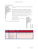
In the unlikely event that the data concerning the operating parameters becomes corrupt the 
system reset option can be used, allowing the processor to restart.

Содержание Grad601

Страница 1: ...Operation Manual for Grad601 Single Axis Magnetic Field Gradiometer System...

Страница 2: ......

Страница 3: ...13 5 Assembly 13 6 Connections 15 7 Grad601 2 Carrying Harness 16 8 Instrument Stands 16 9 Setting Up 17 10 Keypad Operation and Display 17 11 Grid Mode 18 11 1 Main Menu Grid Mode 19 11 2 Set Paramet...

Страница 4: ...40 19 Downloading Survey Data to a PC 42 19 1 Installing the Grad601 Datalog Software 43 19 2 Running the Program 43 19 3 The Save Screen 44 19 4 File Formats 45 20 Serial Output 47 20 1 Data Format 4...

Страница 5: ...TS Page 5 of 61 OM1800 26 A 4 Grids Lines and Positions 56 A 5 Survey Methods 56 A 6 Equipment Required 56 A 7 Setting Out the Area 57 A 8 Setting up the Gradiometer 57 A 9 Logging Data 57 A 10 Other...

Страница 6: ...de 15 Figure 8 Grad601 2 dual sensor gradiometer carrying harness 16 Figure 9 DL601 Data Logger control panel 16 Figure 10 Parallel traverse pattern 30 Figure 11 Zigzag traverse pattern 30 Figure 12 P...

Страница 7: ...ols Glossary The following symbols used within this manual call your attention to specific types of information Caution Indicates a situation in which bodily injury or damage to your instrument or bot...

Страница 8: ...ette battery cassette and either one or two Grad 01 1000L cylindrical gradiometer sensors Figure 1 mounted on a rigid beam Each sensor contains two fluxgate magnetometers with one metre vertical separ...

Страница 9: ...data during each traverse and reduces the survey time and distance walked to one half that of using a single sensor gradiometer Both versions can operate in one of two modes Figure 2 Grad601 2 dual se...

Страница 10: ...les etc without data logging See Grid Mode NMEA NMEA Mode is designed for use with GPS hardware and features an NMEA output The Grid settings are not present and the logger will only run in scan mode...

Страница 11: ...e may become warm during charging This is perfectly normal The red LED on the side of the cassette will be illuminated while the battery is being charged Figure 4b At the end of the charging period th...

Страница 12: ...can be replaced by the operator Remove the back cover of the Battery Cassette Replace the battery or fuse Note When closing the Battery Cassette ensure that an anti surge protection fuse of the type s...

Страница 13: ...logger attached to the beam and one or two separate gradient sensors as appropriate The data logger battery cassette and connecting cables will normally be left attached to the beam which is carried...

Страница 14: ...e underside Figure 7 for securing the unit to the beam The Grad601 1 single sensor gradiometer has the sensor and data logger mounted in front of the operator and the battery box located at the end of...

Страница 15: ...rear of the data logger If two sensors are used connect the sensor to the left of the operator to socket 1 and the one to the right to socket 2 Note Ensure the battery lead to the data logger is conn...

Страница 16: ...n be quickly attached to and detached from the harness using two simple sprung hooks This makes it possible to use more than one harness and operator with one gradiometer The sprung cradles on the abd...

Страница 17: ...ch it will be operating For example if it will be used in the sun let it warm up in the sun rather than in the shade Note The alignment should be checked at intervals over the course of a day by retur...

Страница 18: ...he ENTER key STEP Step through the available options for each of the operating parameters Note With the exception of the ON OFF key the required action occurs only when a key is released after being p...

Страница 19: ...ssing the down and up arrow keys Hence pressing the down arrow will change the display to Start scan Output data After completing each task the program returns to this main menu Note Always return to...

Страница 20: ...ct the traverse pattern to be followed Parallel or Zigzag Lines m 1 Select the required number of data lines per metre 1 2 or 4 Note For a dual sensor system the spacing is fixed at 1 metre so the ope...

Страница 21: ...l indicate that the parameters have been saved before reverting to the main menu Note Once set parameters are saved for use during subsequent operations Selecting Delete data from the main menu will c...

Страница 22: ...nts as well as the specification of your GPS and or data logging device The following options can be set via the Set parameters menu in NMEA Mode Option Default Function Sensors 2 Select the number of...

Страница 23: ...e result is saved to memory with the resolution appropriate for the range selected Each measured value is the average of many samples In Survey Mode the sampling time is adjusted to produce an average...

Страница 24: ...or approaches the sensor The operator should check all parts against the end of a sensor until a change of less than 0 1nT is seen Caution Please ensure that the equipment does not get exposed to stro...

Страница 25: ...set up will only be as good as the area used for the set up so select the area with care 2 Switch on the power using the ON OFF switch select the appropriate settings from the Set parameters menu and...

Страница 26: ...hen the gradiometer is inverted Offset A fixed zero offset error regardless of the orientation of the gradiometer n a Note For optimum results the difference in the gradiometer readings should vary by...

Страница 27: ...2 Align the assembly so the sensor arrows point north and the sensors are vertical then press the green push button When the button is pressed the instrument will take readings from the sensors It wi...

Страница 28: ...lt is indicated and the set up routine will end with the message Coarse Error Sensor followed by the sensor number 1 or 2 Note If the set up is attempted in a relatively high gradient or when some mag...

Страница 29: ...minated using the ESC key 17 Survey Mode Grid Mode 17 1 Survey Parameters The data logger is programmed to record surveys based on a series of areas termed Grids Each Grid will cover an area of 10x10...

Страница 30: ...in either parallel pattern Figure 10 where each traverse starts at the same side of the Grid or zigzag pattern Figure 11 where traverses start at alternate sides of the Grid A zigzag pattern is normal...

Страница 31: ...cted at the distance intervals set by the operator assuming a fixed walking pace The pace can be set as one of the survey parameters between 0 5 and 2m s The operator should find a comfortable walking...

Страница 32: ...Figure 10 or zigzag Figure 11 The Set parameters option allows the initial starting direction to be saved as part of the header information Figure 12 Possible starting points for first traverse Figur...

Страница 33: ...trically in one direction and the values are measured at positions spaced symmetrically along the lines The first line should therefore be measured at a distance of one half line space from the edge o...

Страница 34: ...aken along the line at intervals of 0 5m then the first measurement will be taken at 0 25m from the start of the line and the last at 0 25m from the end of the line The results from each Grid will the...

Страница 35: ...n 5 7 and later allows data to be collected with a line spacing of 1 2 or 4 lines m for both single and dual sensor gradiometers The line spacing is therefore 1 0 5 or 0 25m Using a Grad601 1 single s...

Страница 36: ...or gradiometer for surveying at 2 lines m with a parallel or zigzag traverse pattern the operator must follow exactly the appropriate pattern shown in Figures 17 and 18 Figure 17 Dual sensor parallel...

Страница 37: ...m at 3 25m from edge of the Grid This alternating pattern of 1 5m and 0 5m increments is repeated for the complete Grid 17 4 2 Surveying at 4 lines m When using the Grad601 2 dual sensor gradiometer f...

Страница 38: ...f beam 0 875m from edge of the Grid 3 Centre of beam 1 125m from edge of the Grid 4 Centre of beam at 1 375m from edge of the Grid 5 Made with an increment of 1 25m so centre of beam at 1 625m from ed...

Страница 39: ...e operator to confirm this by pressing the ENTER key The display will then show that the instrument is ready to start the first traverse Note To ensure good alignment of the data the operator should s...

Страница 40: ...s When operating in a zigzag pattern an obstruction may prevent the end of the current traverse and the start of the next traverse being completed Pressing the ESC key at any time during a traverse wi...

Страница 41: ...hown will be incremented accordingly Note Remember that if data is being recorded at 0 25m intervals then four dummy values are required for each metre of traverse If a dummy is entered at the last po...

Страница 42: ...ach recorded Grid separately 18 1 2 Single Shot Operation If Single Shot is selected as Pace in the Set parameters menu between 2 and 0 5m s then the survey operates as normal except that only one rea...

Страница 43: ...ong with appropriate installation software 2 Switch on the data logger it does not need to be connected to any sensors 3 On the PC start the program Grad601 Datalog 4 Select the com port corresponding...

Страница 44: ...hen be saved with filenames comprising the chosen prefix and the Grid number for example if the prefix mygrid is selected the Grids will be saved in files called mygrid1 dat mygrid2 dat etc Skip curre...

Страница 45: ...ll be shown depending on the range used during the survey 19 4 1 Spreadsheet Format If the data has been downloaded in spreadsheet format as one file and opened as tab or comma delimited data in Excel...

Страница 46: ...selected the header and data would appear in separate files with different filename extensions Note If Geoplot by Geoscan Research is being used to view and process the data then it should be download...

Страница 47: ...2 signed integers as 64 bytes and wait for the next character S from the PC The baud rate is set to 9600 baud with 8 data bits no parity 1 stop bit and no handshaking The last transmission may be less...

Страница 48: ...s covered using zigzag traverses then the data will represent this traverse pattern The downloading program uses the header information to re organise the data as if it was collected with a single sys...

Страница 49: ...s The summary data of mean gradient maximum gradient and minimum gradient For a dual sensor gradiometer system the values are those recorded for the left hand sensor One zero value End of File integer...

Страница 50: ...ment is showing abnormally high values and the surrounding area is known to be magnetically quiet then there are several fixes that can be attempted to bring it back to a normal level The gradiometer...

Страница 51: ...ver a memory corruption can sometimes cause the final grid to download in a continuous cycle Note If the number of downloaded bytes exceeds 260 000 then the download should be interrupted manually Aft...

Страница 52: ...y that top and bottom of the sensor are fixed properly with no loose screws the seals on the sensor connector blocks are in good condition If there are any gaps or there is noticeable cracking then a...

Страница 53: ...nd electronic equipment should not be placed in municipal waste Check local regulations for disposal of electronic products 23 1 Waste Electrical and Electronic Equipment WEEE Regulations The Grad601...

Страница 54: ...ata to be plotted with the correct orientation using only the starting direction from the list of parameters saved as a header file Plotting software will normally show a single Grid with the first tr...

Страница 55: ...west lines then continue from the north to the south end of the Grid The adjacent Grid to the south of the completed Grid can then be surveyed and the pattern repeated until a complete column of Grid...

Страница 56: ...d will depend on the purpose of the survey For archaeological prospecting prior to land development the operation may need to be carried out quickly and with the minimum number of personnel Detailed s...

Страница 57: ...up the Gradiometer See also Checking and Adjusting the Sensors Note Ensure that the instrument has been switched on for at least 15 minutes prior to setting up Note Before setting up always check the...

Страница 58: ...The equipment described above is suitable for single or dual sensor operation For the highest spatial accuracy the operator should walk relatively slowly and ensure the sensor is held upright at all t...

Страница 59: ...BARTINGTON INSTRUMENTS Page 59 of 61 OM1800 26 Notes...

Страница 60: ...BARTINGTON INSTRUMENTS Page 60 of 61 OM1800 26...

Страница 61: ...gton Instruments Limited in the following countries United Kingdom Australia Brazil Canada China European Union India Japan Norway and the United States of America Bartington Instruments Limited 5 Tho...

Отзывы: