Operating Instructions
SILAS
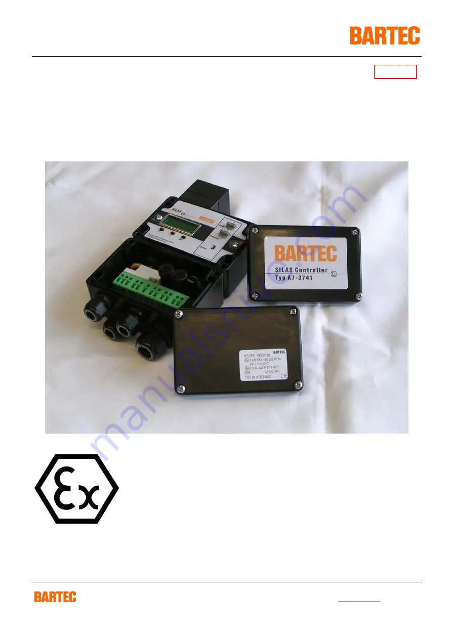
Controller
A7-3741-1110/….
Version 2.00
GmbH
Max-Eyth-Straße 16
Phone: 07931 597-0
E-Mail:
[email protected]
Germany
97980 Bad Mergentheim
Fax: 07931 597-160
Internet:http://www.bartec.de
1021284
Страница 1: ...ing Instructions SILAS Controller A7 3741 1110 Version 2 00 GmbH Max Eyth Straße 16 Phone 07931 597 0 E Mail info bartec de Germany 97980 Bad Mergentheim Fax 07931 597 160 Internet http www bartec de 1021284 ...
Страница 2: ...0 7 Technical Data for the SILAS System Components 11 7 1 SILAS Controller 11 7 2 SILAS Pressure Control Device 13 7 3 SILAS Purge Valve including Leakage Needle Valve 14 7 3 1 Performance Data 14 7 3 2 Assembly 14 7 3 3 Commissioning 14 7 3 4 Adjustment of the Leakage Needle Valve 15 7 4 Pressure Reducer and Leakage Needle Valve 16 7 5 Assembly Set for the Internal Fitting of the SILAS Controller...
Страница 3: ...ller for monitoring pressure in control panels in zone 2 and zone 22 Ex areas It controls the protective gas quantities for a closed control panels and accordingly generates an Ex free area inside the closed control panel The dimensions of the control panel being monitored are optional thanks to the facility of using separate control components SILAS Controller SILAS purge valve SILAS pressure con...
Страница 4: ...Controller in accordance with the intended purpose It is addressed to technically qualified personnel Familiarity with and the technically perfect implementation of the safety instructions and warnings described in this manual are preconditions for safe installation and commissioning The safety notes and warnings given in this documentation are given in a general way and only qualified personnel w...
Страница 5: ...ty devices that have not been affixed correctly or do not function properly e g bridged fuses Non compliance with the instructions in this manual with respect to transport storage assembly commissioning operation maintenance Catastrophic instances due to effects of foreign matter and force majeure We guarantee the SILAS Controller and its accessories for a period of 1 year as of the date of delive...
Страница 6: ... 60 079 14 The unit may be opened only in the manufacturer s works The unit is factory sealed Do not open 4 2 Maintenance When doing maintenance work or servicing and when checking associated equipment adhere to the valid regulations in accordance with Directive 1999 92 EC IEC 60079 19 and EN60079 17 a Installation dismantling operation and maintenance work may only be carried out by trained speci...
Страница 7: ...ave been tightened 4 3 1 Installation Guidelines The potential equalisation connection must be connected to the equipotential bounding conductor in the potentially explosive area As the intrinsically safe circuits are galvanically connected to earth there must be compensation for potential electrical charges over the entire course of the installation of the intrinsically safe circuits The safety a...
Страница 8: ...ing the operating phase If the minimum pressure P 1 in the panel is exceeded during the purging cycle the SILAS Controller connects the purging air nozzle in the input valve If the pressure and accordingly the flow at the pressure control device module switching value of P 3 is sufficient the preset remaining purging time counts down to zero At the end of the pre purging time the purging air nozzl...
Страница 9: ...sed overpressure 5 2 Use in Ex zone 22 In applications in the Ex zone 22 it is essential to clean the control panel inside thoroughly in order to remove dust deposits before the overpressure monitored control panel is switched on for the first time A pre purging cycle functioning in the same way as for the application in zone 2 is not suitable for this purpose During the operating phase the penetr...
Страница 10: ...ounting plate in the control panel An M5 internal thread is available for connecting the reference pressure With the assembly set type 05 0091 0117 optional a connection is produced between the reference pressure and the surrounding atmosphere A through hole of 37 mm is required to mount the pressure control module The outlet screw connection or in the event of outside assembly the lower inlet scr...
Страница 11: ... 20 C Ta 60 C Supply voltage AC 230 V 10 48 62 Hz or AC 115 V 10 48 62 Hz or DC 24 V 10 Max power consumption Pmax 8 W K 2 relay and K3 up to the maximum Tambient 40 C maximum AC 253 V 5 A cos phi 0 7 up to the maximum Tambient 60 C maximum AC 253 V 0 5 A cos phi 0 7 K1 relay up to the maximum Tambient 60 C maximum AC 253 V 0 5 A cos phi 0 7 Permissible ambient temperatures Storage 20 C to 60 C Op...
Страница 12: ...ILAS_E_110806 doc Operating Instructions for the SILAS Controller Technical data are subject to change Dimensions and Fastening Drill Holes Included in the scope of supply 1a SILAS controller 1b Bulkhead screw connection R1 4 x R1 8 1c Sealing brass dia 13mm 1d Sealing polyamide dia 13mm ...
Страница 13: ...ta are subject to change 56 Silas Druckwächter Typ 17 51P3 1604 BARTEC 70 55 Spark resistor O Ring 40 x 2mm Purge gas Inside wall of cabinet 1 hole ø 37 mm Purge gas 7 2 SILAS Pressure Control Device Type 17 51P3 1604 Dimensions 55 x 70 x 56 mm Opening pressure 5 mbar Control panel borehole 37 mm Weight approx 0 2 kg Dimensions for the SILAS pressure control device ...
Страница 14: ...h an internal thread of R 3 8 The purging air nozzle has been screwed in already in the factory The purge valve is fastened with the enclosed bulkhead screw connection R 3 8 x directly at the enclosure As a general rule the purge valve can be mounted in any position but a vertical position is preferable as it prevents the penetration of tiny particles into the inner armature pipe Maximum ambient t...
Страница 15: ...which is accessible through the purging air nozzle must first be closed in a clockwise direction with the aid of a suitable screwdriver Then the necessary leakage air quantity is adjusted by turning to the required value The curve given in the table shows the passage of the air leakage quantity depending on the turns After completing the adjustment the enclosure s overpressure during operation sho...
Страница 16: ...dle valve 05 0056 0015 Control panel borehole 17 mm Maximum input pressure 25 bar Adjustable initial pressure 0 6 bar Material Enclosure zinc die casting sealing NBR Weight pressure reducer 1 8 0 3 kg Weight leakage needle valve 0 05 kg 44 3 0 0 2 5 2 0 1 5 1 0 0 5 0 5 0 4 5 4 0 3 5 40 20 10 30 50 70 60 80 100 90 Rotary Pre pressure rate of leackage l min 45 115 3b 3a 2b 2a Cabinet 2a pressure red...
Страница 17: ... will be used when the SILAS Controller has to be mounted inside the Ex pz panel In this case the conection for the referenz of the atmosphaerepressure has to be directed with a tube to the outside Type 05 0091 0117 Component parts 1 connection for the SILAS output M 5 x hose 4 mm 1 atmosphere connection R 1 8 x hose 4 mm 2 m hose 4 mm 1 set of assembly instructions 4a Flow connector section A 4b ...
Страница 18: ...fuse This fuse serves to protect a digital purge valve connected to the terminals 6 10 and 13 The fuse rating may not exceed the value of 3 x INominal of the valve s nominal current Observe the following when changing Disconnect from voltage supply before changing the integrated SI 1 valve fuse Factory fitted fuse values mains voltage AC 230 V 80 mA AC 115 V 160 mA DC 24 V 500 mA 13 N L 7 8 9 10 1...
Страница 19: ...th the and keys They are saved by pressing the SET key The saved value is marked by a The switching states of the K1 K 2 and K 3 relays are displayed by means of LEDs K 1 K 2 and K 3 whereby the LEDs light up when the respective relay has picked up 9 1 S 1 Rotary Switch When the S1 rotary switch is at pos 1 the SILAS Controller is switched on If the SILAS Controller is switched off the last displa...
Страница 20: ...RG YP1 YES YES NO NO PRG YP2 YES YES NO YES PRG YP3 YES YES YES NO 1 Pre purge function PRG NO NO NO NO NO 2 Pre purging time min sec P T Pre purging time if a pre purging cycle PRG Y _ is activated 3 Pressure value P 1 mbar P 1 MIN disconnection threshold 4 Pressure value P 2 mbar P 2 a Pre alarm b If a purge valve is connected the purge valve switches the purging air nozzle on briefly if the val...
Страница 21: ...ue falls short of the P 2 pressure P 3 Purge pressure Switches on if the P 3 pressure value is exceeded P 4 Maxalarm Switches on if the P 4 pressure value is exceeded PT Purge timet Switches on when the purging time counts down BYP Bypass Switches on if the bypass is activated 7 Function of Relais K 3 ALR Functions Alarm Switches off in the event of internal malfunctioning 8 Time delay sec DLY Gen...
Страница 22: ...e 80 mA time lag Mains voltage AC 115 V valve fuse 160 mA time lag Mains voltage DC 24 V valve fuse 500 mA time lag 10 2 K2 Relay The K 2 relay signalises the enabling and switches on if in zone 2 Use PRG YES the pre purging time has ended and the pressure value of P1 is exceeded or if in zone 22 Use PRG NO only the pressure value of P1 is exceeded The K 2 relay stays switched on if the value fall...
Страница 23: ...s on The bypass function is deactivated by removing the bypass bridge or altering the S 2 switch position Ex Protection Bypassing Commissioning with bypass key operated switch requires the approval of the works supervisor or his appointee Approval may only be given if it has been ensured that there will not be any explosive atmosphere for the duration of the necessary work or if the necessary prot...
Страница 24: ...urging flow l h x 60 purging time minutes Example enclosure capacity 200 litres purging and 10 times the enclosure capacity Setting of switching value P 3 12 5 mbar Resulting flow rate in accordance with diagram 15000 l h Purging time 200 l x 10 15000 l x 60 9 9 minutes 8 minutes 00 seconds with the use of 1 x type 17 51P3 1604 pressure control device Purging time 200 l x 10 15000 l x 30 4 5 minut...
Страница 25: ...crease the input pressure to the setpoint value Check if the purging air nozzle has the correct value Insufficient purge gas flow through the control panel Check if the P 1 pressure switch has the correct value The purging time does not begin to count down Required pressure is not reached in the pressure reducer Purge gas supply is too low Increase the cross section of the supply line Check the va...
Страница 26: ...ent consumption Maximum power dissipation Date of production AC V A W Purge valve Digital valve 0 does not exist 1 exist Purging air nozzle ø mm Type of function Compensation of leakage losses 1 constant purging 2 Purging medium Instrument air 1 Inert gas 2 Leakage losses maximum l min SCC Capacity Dimensions W x H x D mm litres Purge gas flow rate In accordance with the diagram the purge gas flow...
Страница 27: ...1 5 mbar P3 S1 Pos 5 Minimum overpressure between enclosure and atmosphere purging pressure 15 0 mbar P4 S1 Pos 6 The maximum overpressure between enclosure and atmosphere disconnection threshold 20 0 mbar Delay S1 Pos 7 General time delay of relays K1 to K 3 for fluctuations in the pressure air 5 seconds K 3 S1 Pos 8 Function of K 3 relay K 2 relay switching simultaneously with K 2 K 2 Pressure t...
Страница 28: ...r 17 51P3 1604 SILAS Purge valve for Ex zones 2 22 Supply voltage AC 230 purging air nozzle 2 8 and 3 9 mm 03 5110 0026 SILAS Purge valve for Ex zones 2 22 Supply voltage AC 115 purging air nozzle 2 8 and 3 9 mm 03 5110 0028 SILAS Purge valve for Ex zones 2 22 Supply voltage DC 24 purging air nozzle 2 8 and 3 9 mm 03 5110 0029 Pressure reducer Connection maximum flow 20m m 05 0056 0007 Pressure re...
Страница 29: ...ppendix A to the Operating Instructions SILAS Controller Declaration of EC Conformity Page 29 of 29 SILAS_E_110806 doc Operating Instructions for the SILAS Controller Technical data are subject to change ...