Manual 2100-495A
Page
2 of 21
CONTENTS
BARD MANUFACTURING COMPANY, INC.
BRYAN, OHIO USA 43506
Figures
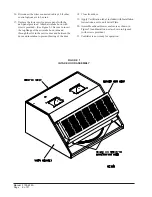
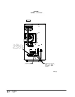
Figure 1 Intake Hood Assembly ............................ 6
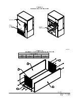
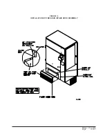
Figure 2 Remove Vent Option Door ...................... 7
Figure 2A Assembly of Exhaust Blower Enclosure ... 7
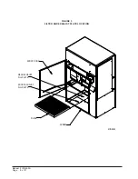
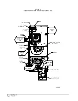
Figure 3 Filter & Exhaust Plate Location .............. 8
Figure 4 Installation of Exhaust Blower Assembly ... 9
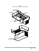
Figure 5 Installation of WFERV ........................... 10
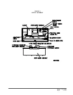
Figure 6 WFERV Assembly .................................. 11
Figure 7 Wiring - 230 Volt ................................... 12
Figure 8 Installation of Fresh Air Intake
Hood Assembly ..................................... 13
Figure 9 Operation of Unit with WFERV ............. 14
Figure 10 Thermostat Wiring ................................ 18
Figure 11 Terminal Block Location Diagram ......... 19
Figure 12 Hub Assembly with Ball Bearings ......... 20
Tables
Table 1
Ventilation Air (CFM) ................................ 16
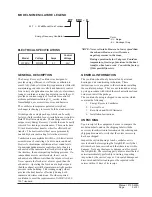
Model Nomenclature Legend ..................................... 3
Electrical Specifications ............................................. 3
General Description ................................................... 3
General Information ................................................... 3
Unpacking .................................................................. 3
Performance and Application Data - WFERV ............ 4
Basic Installation (Field Installation) ................... 5 & 6
Basic Installation (Factory Installed Versions) ......... 15
Control Wiring .......................................................... 15
Control Requirements .............................................. 15
Recommended Control Sequences ......................... 15
Ventilation Airflow .................................................... 15
Energy Recovery Ventilator Maintenance ............... 16
Maintenance Procedures ......................................... 16
Quarterly & Annual Maintenance ............................. 17
Wiring Diagram ........................................................ 21
Содержание WFERV-A-X
Страница 10: ...Manual 2100 495A Page 10 of 21 FIGURE 5 INSTALLATION OF WFERV...
Страница 11: ...Manual 2100 495A Page 11 of 21 FIGURE 6 WFERV ASSEMBLY...
Страница 13: ...Manual 2100 495A Page 13 of 21 FIGURE 8 INSTALLATION OF FRESH AIR INTAKE HOOD ASSEMBLY...
Страница 18: ...Manual 2100 495A Page 18 of 21 FIGURE 10 THERMOSTAT WIRING DIAGRAM...
Страница 19: ...Manual 2100 495A Page 19 of 21 FIGURE 11 TERMINAL BLOCK LOCATION...
Страница 20: ...Manual 2100 495A Page 20 of 21 FIGURE 12 HUB ASSEMBLY WITH BALL BEARING...
Страница 21: ...Manual 2100 495A Page 21 of 21...


